はじめに
内部必須条件
必要な工具と部品
-
-
スパッジャーの平面側先端を使って、 AirPort/Bluetoothカード上のソケットから両方のアンテナケーブルコネクタを持ち上げます。
One of my terminals is broken. What solutions do you recommend me
Omar Lopez - 返信
You’re actually pushing the connector from side to side toward the front of the case (or towards the track pad). It’s not a vertical motion at all.
Jay Quilty - 返信
I’d also mention to be careful taking these off and putting them back on. I also accidentally pulled a terminal off it’a cable.
If the process is taken to replace the top case, you can leave the AirPort card hanging from the antenna wires. Only remove the card’s retaining screw and slide the card to the right (direction of the antenna connectors) to separate it from the main board.
-
-
-
スパッジャーの先端を使って、カメラケーブルコネクタの接続を外します。
-
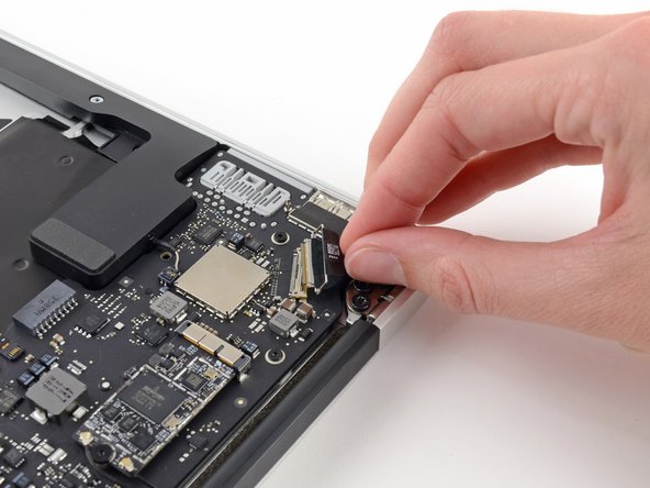
カメラケーブルをI/Oボードの表面と並行に、本体の前面端に向けて引っ張り、接続を外します。
You’ve missed a whole section here on removing the fan. It’s still present in Step 19 pics, but gone by Step 23. It’s not that it’s difficult to work out how to do it. But, when reassembling and following the steps in reverse, it’s handy to know when to use which screws!
Ah! –my bad. The steps for removing Fan etc. are there –up round Step 13. It’s just your photos that are slightly out of sync, as it’s back in place again by Step 19. So, while working in reverse, it looks like it’s not been covered.
On getting it on — i feel it's implied by the word "push” you can walk it out with the spudger. I couldn't wanage that, and instead walked it out by taking the cord between my index and thumb and walking it out by pulling it to the right and then the left repeatedly in a
-
-
-
-
スパッジャーの先端を使って、キーボードバックライトのリボンケーブルのZIFソケット上の固定フラップを持ち上げます。
-
スパッジャーを使って、キーボードのバックライトリボンケーブルをソケットから引き抜きます。
Do you know where i can buy the retaining clip ?
Not sure you can. I’d just use some kapton tape to hold it in place and call it good.
-
-
-
スパッジャーの平面側先端を使って、ロジックボードのソケットから右側スピーカーのケーブルコネクタを持ち上げて、接続を外します。
What is this cables for?
It’s a speaker cable
This is the one that gave me the hardest time!!! It does pop up and out tho.
-
-
-
上部ケースにロジックボードを固定している、6.3mmT5トルクスネジを6本外します。
When re-assembling the motherboard, attach all 6 screws but do not completely tighten yet.
First make sure the rubber gasket is sitting properly, that the 7th screw hole (from Step 18) is properly aligned, and the Airport wire is sitting properly and also not caught under the heat sink.
Once everything is well aligned, start tightening the screws while watching out for the alignment. I found it useful to keep an eye on screw-hole from Step 18 as a reference.
Going in this order, there is a 7th screw securing the logic board to the frame; the heatsink is secured to the logic board with 4 screws, and secured to the frame with 1 more screw. Either take the heatsink off first, or remove that last screw underneath two small black wires, next to the left (as viewed when using the computer; if the computer is flipped over with the cover off and the monitor hinge end of the computer farthest from you, it is in the far right corner) set of three big torx screws that hold the hinge in place. The exact location of this screw is pictured in step 35's second picture; the screw goes through the loop visible below the rubber fan insulator. Scoot those 2 li'l wires out of the way and remove that screw, then the logic board comes right out. If this isn't clear, please let me know and I'll try to describe it better, or add a photo. If I'm posting this to the wrong instruction page, let me know; I was pretty sure I correctly identified my rig, but if not, sorry for the N00bage.
I got an extra screw hiding under the rubber gasket holding the end of the heatsink to the chassis. Ended up bending the heatsink a little cause I wasn't looking for it.
“Samsung RAM module”… do you mean the SSD? That stick of NVRAM is totally your hard drive.
Exactly, he means SSD (storage) the RAM (memory) is soldered to this 820-00165 logic board. Also on this model the 2015 MBA there is no logic board retaining screw under the SSD
-
-
-
アンテナケーブルリテイナーと左側のクラッチヒンジを上部ケースに固定している、内側の4.9mm T8トルクスネジを2本外します。
This is the same screws as step 17.
Joseph Lee - 返信
Good catch! We did some sleuthing and it looks like a couple guides did indeed have an extra section of steps! All better now =)
In my computer these screws were the same size as the other side’s hinge screws. All 6 are the same size.
-
-
-
アンテナケーブルのリテイナーをわずかに押し出して、上部ケースとヒートシンクの先端を固定している3mm T5トルクスネジを外します。
It’s not clear what you mean by “This step is not needed.” If you want to remove the logic board from the upper case in order to put it onto your replacement upper case, you will have to remove this screw.
This step is only needed if you’re replacing the ENTIRE top case. Simply swapping out the trackpad unit does not make this step necessary. This entire tutorial assumes you’re replacing the entire top case which is an expensive mistake if you’re simply replacing the trackpad and/or keyboard. The keyboard is removable as well despite those many tiny rivets. Save money and time by not replacing the entire top case for a bad trackpad and/or keyboard. I needed to accomplish this step because I also removed and replaced the keyboard.
NOTE: There is a sort of clamp/washer attached to this screw that I didn’t know about until I flipped the laptop up on its side and it fell onto the desk. Also: you need to reset it *before* the motherboard
In my computer this screw was not there, nor was a related washer. I got it used so perhaps someone has already been there and did not replace the screw.
Also, the photo here shows how this end of the fan gasket is placed
.
-
-
-
スパッジャーの平面側先端を右側スピーカーの下にスライドして差し込み、接着剤を緩めます。
-
右側スピーカーを、上部ケースから取り出します。
You don’t really *have* to remove the speaker, especially if your replacement upper case assembly already includes the speakers.
I found the same. If you already have speakers in your new upper case, you can leave them. When you put the logic board back in, it will be a tight fit. I had to start with the corner near the right hinge (the Thunderbolt port corner) and work it in to place.
If it is difficult to remove the speakers you can use Isopropyl Alcohol to loosen the adhesive holding the speakers in place. Make sure to keep the Isopropyl Alcohol away from the speaker itself.
BluRepairs - 返信
-
-
-
慎重にロジックボードアセンブリを上部ケースから取り出します。ケーブルが絡んでいないかご注意ください。
-
ボードから緩いケーブルを離して、ボードの下に挟まらないようにします。
-
2番目の画像でハイライトされているように、アンテナケーブルがそれぞれの切り欠きに挿入されているか確認します。
It’s probably worth mentioning here that during reassembly you want to tuck the rubber gasket under the extension of the heat sink that the fan slots into.
-


デバイスを再組立する際は、これらのインストラクションを逆の順番に従って作業を進めてください。
デバイスを再組立する際は、これらのインストラクションを逆の順番に従って作業を進めてください。
ある他の人がこのガイドを完成しました。
以下の翻訳者の皆さんにお礼を申し上げます:
100%

Midori Doiさんは世界中で修理する私たちを助けてくれています! あなたも貢献してみませんか?
翻訳を始める ›
