メインコンテンツにスキップ

このバージョンは誤った内容を含んでいる可能性があります。最新の承認済みスナップショットに切り替えてください。

必要な工具と部品

  1. , 下部ケース: 手順 1、 1の画像 1
    この手順で使用する道具:
    P5 Pentalobe Screwdriver Retina MacBook Pro and Air
    $11.99
    購入する
    • まず、コンピューターをシャットダウンし、柔らかい素材の表面上に天面を下にして置きます。

    • 以下の10本のネジを外します:

    • 星型ペンタローブネジ 8mm 2本

    • 星型ペンタローブネジ 2.5mm 8本

    • 星型ペンタローブネジを外す際に必要な特別ドライバーはこちらで購入できます。

  2. : 手順 2、 1の画像 1
    • ディスプレイと下部ケースの間に指を入れ、下部ケースを引き上げて外します。

  3. , バッテリーコネクター: 手順 3、 2の画像 1 , バッテリーコネクター: 手順 3、 2の画像 2
    • 作業中に部品がショートするのを防ぐためにバッテリーを取り外します。

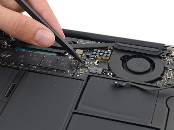
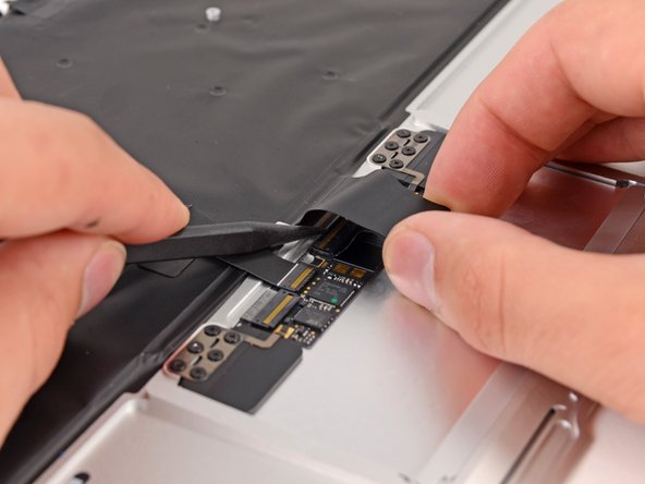
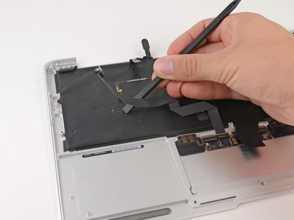
    • スパッジャーの平面側先端を利用し、バッテリーコネクターを持ち上げてロジックボードのソケットから外します。

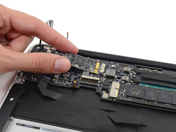
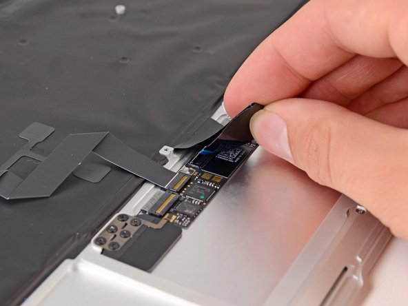
    • ロジックボードから外したコネクターのケーブルをわずかに曲げて、コネクター部分が誤ってソケットに接触しないようにします。

  4. , I/Oボードケーブル: 手順 4、 2の画像 1 , I/Oボードケーブル: 手順 4、 2の画像 2
    • スパッジャーの平面側先端を使って、I/Oボード上の各ソケットから左右のI/Oボードケーブルコネクタを持ち上げます。

  5. : 手順 5、 1の画像 1
    • I/Oボードケーブルを持ち上げて外します。

  6. , ファン: 手順 6、 2の画像 1 , ファン: 手順 6、 2の画像 2
    • スパッジャーの先端を使って、iSightカメラケーブルのコネクタの両側を慎重に押さえて、ロジックボード上のソケットからコネクタの接続を緩めます。

    • ソケットからコネクタを外す際は、慎重にずらしながら作業を行なってください。

  7. : 手順 7、 2の画像 1 : 手順 7、 2の画像 2
    • ファンに留められた接着剤からiSightカメラケーブルを剥がします。

  8. : 手順 8、 2の画像 1 : 手順 8、 2の画像 2
    • スパッジャーの先端を使って、ファンケーブルのZIFソケット上の固定フラップを注意深く跳ね上げます。

    • ソケットではなく、蝶番で動く固定フラップのみを跳ね上げているか確認してください。

  9. : 手順 9、 1の画像 1
    • 上部ケースをファンに固定している次の3本のネジを外します。

    • 5.5 mm T5トルクネジー2本

    • 4.6 mm T5トルクネジー1本

    • あるモデルによっては、このサイズの代わりに3.6 mm T5トルクネジが使用されています。

  10. : 手順 10、 3の画像 1 : 手順 10、 3の画像 2 : 手順 10、 3の画像 3
    • ファンを持ち上げますが、上部ケースの底からファンを完全に取り出さないでください。

    • Airからファンを取り出す際に、ソケットからファンのリボンケーブルを慎重に引き抜いてください。

  11. , ロジックボードアセンブリ: 手順 11、 3の画像 1 , ロジックボードアセンブリ: 手順 11、 3の画像 2 , ロジックボードアセンブリ: 手順 11、 3の画像 3
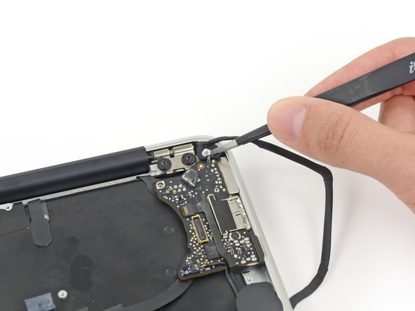
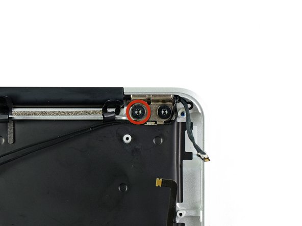
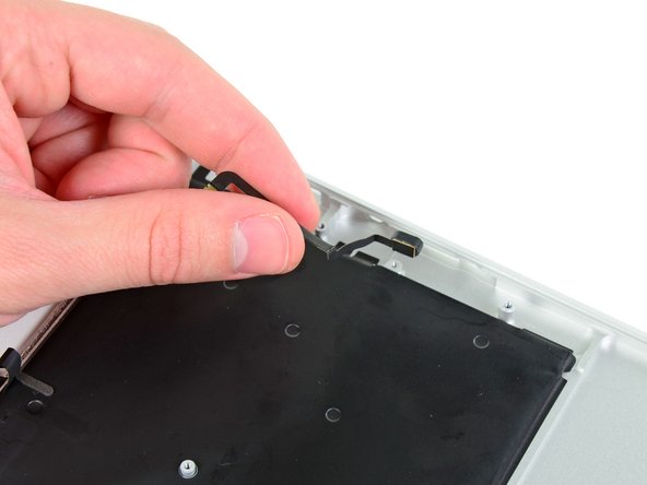
    • スパッジャーの平面側先端を使って両側のアンテナコネクタをAirPort/Bluetoothカード上のソケットから引き抜き、作業の邪魔にならないように動かします。

  12. : 手順 12、 1の画像 1
    • バッテリーを上部ケースに固定している次のネジを外します。

    • 5.2 mm T5 トルクネジー2本

    • 6 mm T5トルクネジー1本

    • 2.6 mm T5トルクネジー2本

  13. : 手順 13、 1の画像 1
    • バッテリーの作業中は、6つのリチウムポリマーバッテリーセルを触ったり、握ったりしないでください。

    • ロジックボード付近の端からバッテリーを持ち上げて、上部ケースから取り出します。

  14. : 手順 14、 2の画像 1 : 手順 14、 2の画像 2
    • ロジックボード上のソケットから電源ケーブルを引き抜いて、I/Oボードの接続を外します。

    • Airの正面端に向けて、ロジックボードの表面と並行にケーブルを引きます。

  15. : 手順 15、 3の画像 1 : 手順 15、 3の画像 2 : 手順 15、 3の画像 3
    • スパッジャーの先端を使って、ロジックボード上の切り欠きからアンテナケーブルを巻き戻して外します。

  16. : 手順 16、 3の画像 1 : 手順 16、 3の画像 2 : 手順 16、 3の画像 3
    • ディスプレイデータケーブルのロックに付いている黒いプラスチックのフラップの下に、スパッジャーの先端を慎重に差し込んで、ロックをソケットから上向きに出します。

    • ロックをソケットから押し出しながら、ディスプレイデータケーブルをソケットから慎重に引き抜きます。

    • ディスプレイデータケーブルを外す際に上向きに引っ張ると、ソケットがロジックボードにダメージを与えてしまう可能性があります。ご注意ください。

  17. : 手順 17、 3の画像 1 : 手順 17、 3の画像 2 : 手順 17、 3の画像 3
    • スパッジャーの先端を使って、スピーカーケーブルのコネクタの下に差し込んで、ソケットからまっすぐ持ち上げます。

    • ロジックボード上の切り欠きからケーブルを慎重に通して外します。

  18. : 手順 18、 3の画像 1 : 手順 18、 3の画像 2 : 手順 18、 3の画像 3
    • スパッジャーの先端もしくは指先を使って、トラックパッドのリボンケーブルZIFソケット上の固定フラップを持ち上げます。

    • ソケット自体ではなく、ヒンジの付いた固定フラップを持ち上げているか確認してください。

    • トラックパッドのリボンケーブルを、Airの正面端に向けてソケットからまっすぐ引き抜きます。

  19. : 手順 19、 3の画像 1 : 手順 19、 3の画像 2 : 手順 19、 3の画像 3
    • スパッジャーの先端を使って、キーボードバックライトのリボンケーブルZIFソケット上の固定フラップを持ち上げます。

    • ソケット自体ではなく、ヒンジの付いた固定フラップを持ち上げているか確認してください。

    • キーボードのバックライトリボンケーブルをソケットから引き抜きます。

  20. : 手順 20、 1の画像 1
    • ロジックボード上のAirPort/Bluetoothカードを固定している2.9 mm T5トルクネジを1本外します。

  21. : 手順 21、 3の画像 1 : 手順 21、 3の画像 2 : 手順 21、 3の画像 3
    • AirPort/Bluetoothボードの外れている側先端をわずかに持ち上げて、ロジックボード上のソケットから引き抜きます。

    • ロジックボード上のソケットにダメージを与えないように、AirPort/Bluetoothカードを持ち上げすぎないようにご注意ください。

  22. : 手順 22、 1の画像 1
    • 上部ケースとロジックボードを固定している3.6 mm T5トルクネジを3本外します。

    • あるモデルによっては、3.1 mm T5トルクネジが使用されています。

  23. : 手順 23、 3の画像 1 : 手順 23、 3の画像 2 : 手順 23、 3の画像 3
    • ヒートシンク端をロジックボードアセンブリを慎重に持ち上げて、上部ケースのポート側から引き抜いて、Air本体より取り出します。

    • ロジックボードを交換する際は、ボードのポート側ラバーガスケットの下にラバーエッジを差し込み、それからボードを押して固定します。

  24. , I/Oボード: 手順 24、 3の画像 1 , I/Oボード: 手順 24、 3の画像 2 , I/Oボード: 手順 24、 3の画像 3
    • I/Oボードに近い上部ケースの角から、小さなゴムパッキンを取り外します。

    • ディスプレイケーブルコネクタに近い角からガスケットを取り外します。

  25. : 手順 25、 2の画像 1 : 手順 25、 2の画像 2
    • 必要に応じて、ピンセットを使って、マイクケーブルのZIFコネクタを覆っているテープがあれば剥がします。

  26. : 手順 26、 3の画像 1 : 手順 26、 3の画像 2 : 手順 26、 3の画像 3
    • スパッジャーの先端を使って、マイクケーブルZIFソケットの固定フラップを慎重にめくってください。

    • ソケット本体ではなく、留め具のフラップをこじ開けるようにしてください。

    • ピンセットでマイクリボンケーブルをソケットからまっすぐ引き抜きます。

  27. : 手順 27、 3の画像 1 : 手順 27、 3の画像 2 : 手順 27、 3の画像 3
    • スパッジャーの先端を使って、コネクタの近くにあるピーカーケーブルの下に差し込んでこじ開けて、ソケットからまっすぐ持ち上げます。

    • ロジックボードの凹みからケーブルを解きます。

  28. : 手順 28、 1の画像 1
    • I/Oボードを上部ケースに固定している3.6mmT5トルクスネジ1本を外します。

  29. : 手順 29、 3の画像 1 : 手順 29、 3の画像 2 : 手順 29、 3の画像 3
    • 電源ケーブルでI/Oボードを慎重に持ち上げて、ケースの端から引き離します。

  30. , ディスプレイアセンブリ: 手順 30、 3の画像 1 , ディスプレイアセンブリ: 手順 30、 3の画像 2 , ディスプレイアセンブリ: 手順 30、 3の画像 3
    • 上部ケースにアンテナケーブルを固定している6本のケーブルループを剥がします。

    • モデルによってはケーブルループが7本の場合があります。

    • ケーブルループを上部ケースのチャンネルカットから一度に引き抜きます。

    • ここに翻訳を挿入する

  31. : 手順 31、 2の画像 1 : 手順 31、 2の画像 2
    • 各ディスプレイヒンジを上部ケースに固定している内側の4.9mmT8トルクスネジ(合計2本)を外します。

  32. : 手順 32、 1の画像 1
    • ディスプレイを上部ケースと垂直になるまで開き、図のようにテーブルの上に置きます。

    • Airを固定したまま、下部ディスプレイブラケットから残りの4.9mmT8トルクスネジを外します。

  33. : 手順 33、 1の画像 1
    • 最後のディスプレイのネジを外す前に、もう片方の手でディスプレイと上部ケースをしっかりと固定してください。テーブルの上に落下してしまうと、高価な部品が破損の原因となることがあります。

    • ディスプレイを上部ケースに固定している最後の4.9mmT8トルクスネジを外します。

  34. : 手順 34、 2の画像 1 : 手順 34、 2の画像 2
    • 上部ケースをディスプレイアセンブリ側に少し押し、ディスプレイアセンブリの前面から回転させて離します。

    • 2つのディスプレイヒンジが上部ケースから乖離したら、ディスプレイを取り出します。

  35. この手順は未翻訳です。 翻訳を手伝う。

    : 手順 35、 2の画像 1 : 手順 35、 2の画像 2
    • Use the flat end of a spudger to pry the right speaker off the adhesive securing it to the upper case.

    • Only pry up on the speaker from the areas of bare aluminum on the upper case. Prying up from the keyboard area may damage the keyboard and the speaker itself.

    • Remove the right speaker from the upper case.

  36. この手順は未翻訳です。 翻訳を手伝う。

    : 手順 36、 2の画像 1 : 手順 36、 2の画像 2
    • Use the flat end of a spudger to pry the left speaker off the adhesive securing it to the upper case.

    • Only pry up on the speaker from the areas of bare aluminum on the upper case. Prying up from the keyboard area may damage the keyboard and the speaker itself.

    • Remove the left speaker from the upper case.

  37. この手順は未翻訳です。 翻訳を手伝う。

    : 手順 37、 2の画像 1 : 手順 37、 2の画像 2
    • Use the tip of a spudger to pry the microphone away from the side of the upper case.

    • Remove the microphone from the upper case.

    • Upper case remains.

  38. この手順は未翻訳です。 翻訳を手伝う。

    : 手順 38、 3の画像 1 : 手順 38、 3の画像 2 : 手順 38、 3の画像 3
    • The ZIF connector for the keyboard ribbon cable is hidden under the cable itself.

    • Push/lift the keyboard ribbon cable off of the upper case with one hand.

    • With the other hand, use a spudger to flip up the retaining flap on the ZIF connector.

    • Once the retaining flap has been flipped up, carefully pull the ribbon cable straight out of its socket.

  39. この手順は未翻訳です。 翻訳を手伝う。

    : 手順 39、 2の画像 1 : 手順 39、 2の画像 2
    • Use the flat end of a spudger to separate the trackpad ribbon cable from the underside of the keyboard.

    • The cable is held in place with adhesive. Work carefully, and be sure to not let the spudger slip and damage any components.

  40. この手順は未翻訳です。 翻訳を手伝う。

    : 手順 40、 1の画像 1
    • Remove the six 1.5 mm Phillips #00 screws securing the trackpad to the upper case.

    • Check your replacement upper case—if it doesn't have this wide T5 screw, remove it to transfer into the replacement.

    • This is an adjustment screw to set the distance of the click of the trackpad—on reassembly, test the click and adjust this screw until it feels right.

  41. この手順は未翻訳です。 翻訳を手伝う。

    : 手順 41、 3の画像 1 : 手順 41、 3の画像 2 : 手順 41、 3の画像 3
    • Holding the upper case up off the table with one hand, gently push the trackpad up through the upper case.

    • Remove the trackpad from the upper case.

  42. : 手順 42、 1の画像 1
    • 上部ケースが残ります。

ゴール

15 の人々がこのガイドを完成させました。

作成者

2人の作成者と共同で作成されました。

Sam Goldheart

メンバー登録日: 10/18/12

465,870 ポイント

538のガイドは作成済み

チーム

iFixit iFixit人のメンバー

Staff

135 メンバー

17,228のガイドは作成済み

5 件のコメント

Thanks to Sam Lionheart for this guide! Yes difficult but a great step by step guide!

A member of our family had a coffee spill on their MacBook Air 11". The Apple Store said the machine was "dead" forever and encouraged us to buy new. I used this guide to take the Air apart, clean it, and put it back together. The Air is now working, it has some minor glitches so we will have to watch it and keep the data backed-up. But it works.

The hardest parts, where I wished there was more hints - helps, were putting the Air back together at: #38 reattaching the larger ZIF connector and #15 reattaching the antenna cables.

David - 返信

Thanks to this guide, it was easy. Took me about 2.5 hours total, no problems after re-assembly.

Check your replacement part, mine included cable loops and microphone already installed, so I did not need to remove during disassembly.

Thanks Sam & ifixit!!

Ben Mishkin - 返信

Used this guide to replace the keyboard and backlight to my MacBook Air 11” early 2014 A1465! Had to accompany the repair with a few videos on YouTube for help with KB removal and reinstall. Apple charges 231 including labor and iFixit charges $220 for the top cover, but it’s not necessary. Ordered the KB, backlight, and extra set of screws (for the KB) on EBay for about $25 total Installing the 50+ KB screws was very tedious and routing the antenna was a pain, but worth saving $200!

Daniel Cho - 返信

Very good guide. I discovered some a missing screw and gasket. Steps are accurate although I did it in a different order.

watertubigh2o - 返信

My 5 year old spilled a glass of water on the keyboard and after opening and putting the computer upside down for a couple of days, it would not do anything. After sitting dead for a month I decided to crack it open. I found a bunch of corrosion (no surprise) on the logic board and some of the connectors and cleaned it all with alcohol. When I put everything back together, the computer actually began charging and was awakened from its sleeping state. However, the keyboard was not working properly, so I decided to order this upper case. While tedious, the replacement was not too difficult. When I finished and powered on, it started up no problem, but it would not connect to the internet (wifi connected, just no internet). A simple restart fixed this issue. Now, the only issue I’m dealing with is that the left “shift,” “opt/alt,” and '“ctrl” keys do not work. The standard advice is to reset the SMC, but this requires the use of the affected keys. Please help!

Aaron Smela - 返信

コメントを追加

統計データ:

過去 24時間: 0

過去 7 日: 9

過去 30 日: 34

今までの合計 8,907