メインコンテンツにスキップ

Mac mini Mid 2010 Logic Board Replacement

必要条件のみ
この修理ガイドは、他のガイドの前提条件として使用されます。それ自体は不完全で、単独で使用されることはありません。
  1. Mac mini Mid 2010 Logic Board Replacement, Logic Board: 手順 1、 1の画像 1
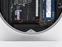
    • Remove the following three screws:

    • One 5.0 mm T8 Torx or 2.0 mm Hex screw (either will work)

    • One 16.2 mm T6 Torx screw

    • One 26 mm T6 Torx standoff

  2. Mac mini Mid 2010 Logic Board Replacement: 手順 2、 2の画像 1 Mac mini Mid 2010 Logic Board Replacement: 手順 2、 2の画像 2
    • Carefully pull the wires for both hard drive thermal sensors upward to lift their connectors up and out of the sockets on the logic board.

  3. Mac mini Mid 2010 Logic Board Replacement: 手順 3、 2の画像 1 Mac mini Mid 2010 Logic Board Replacement: 手順 3、 2の画像 2
    • Use the flat end of a spudger to pry both the hard drive and optical drive connectors up out of their sockets on the logic board.

  4. Mac mini Mid 2010 Logic Board Replacement: 手順 4、 1の画像 1
    • To disconnect the optical drive thermal sensor, pinch its cables between your thumb and a spudger and pry the spudger upward to lift the connector up and out of its socket on the logic board.

  5. Mac mini Mid 2010 Logic Board Replacement: 手順 5、 1の画像 1
    • Use the tip of a spudger to lift the IR sensor connector up and out of its socket on the logic board.

  6. Mac mini Mid 2010 Logic Board Replacement: 手順 6、 3の画像 1 Mac mini Mid 2010 Logic Board Replacement: 手順 6、 3の画像 2 Mac mini Mid 2010 Logic Board Replacement: 手順 6、 3の画像 3
    この手順で使用する道具:
    Mac mini Logic Board Removal Tool
    $4.99
    購入する
    • To remove the logic board, two cylindrical rods must be inserted into the holes highlighted in red. Inserting instruments into any logic board holes other than the ones highlighted in red may destroy the logic board.

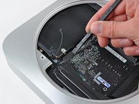
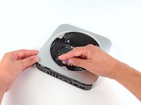
    • Insert a Mac mini Logic Board Removal Tool into the two holes highlighted in red. Be sure it makes contact with the outer case below the logic board before proceeding.

    • If you don't have a Logic Board Removal Tool handy, you can use two tools having a maximum diameter of 2.5 mm instead. Just insert one into each of the highlighted holes.

    • Carefully pull the tool toward the I/O board. The logic board and I/O board assembly should slightly slide out of the outer case.

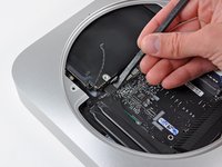
    • Cease prying when the I/O board is visibly separated from the outer case. Remove the Mac mini Logic Board Removal tool.

  7. Mac mini Mid 2010 Logic Board Replacement: 手順 7、 1の画像 1
    • Simultaneously push the two plastic clips on the far left and right sides of the I/O board toward the middle of the I/O board and pull the I/O board away from the outer case.

  8. Mac mini Mid 2010 Logic Board Replacement: 手順 8、 1の画像 1
    • Pull the I/O board/logic board assembly out of the outer case enough to access the power connector.

    • Use a pair of tweezers to disconnect the power cable from the logic board.

    • Pull the power cable connector toward the optical drive opening.

  9. Mac mini Mid 2010 Logic Board Replacement: 手順 9、 1の画像 1
    • Carefully slide the logic board assembly out of the mini, minding any cables that may get caught.

終わりに

To reassemble your device, follow these instructions in reverse order.

作成者

8人の作成者と共同で作成されました。

Andrew Bookholt

585,718 ポイント

619のガイドは作成済み

0 件のコメント

コメントを追加

統計データ:

過去 24時間: 0

過去 7 日: 0

過去 30 日: 0

今までの合計 1,622