メインコンテンツにスキップ

この翻訳は、ソースガイドの最新の更新を反映していない可能性があります。 翻訳の更新に協力してください。 または ソースガイドを参照してください

Mac Pro Late 2013 ロジックボードの交換

必要な工具と部品

  1. Mac Pro Late 2013 ロジックボードの交換, アウターケース: 手順 1、 2の画像 1 Mac Pro Late 2013 ロジックボードの交換, アウターケース: 手順 1、 2の画像 2
    • ロックスイッチを右側にスライドして、ロックを解除します。

  2. Mac Pro Late 2013 ロジックボードの交換: 手順 2、 3の画像 1 Mac Pro Late 2013 ロジックボードの交換: 手順 2、 3の画像 2 Mac Pro Late 2013 ロジックボードの交換: 手順 2、 3の画像 3
    • Mac Proからアウターケースをまっすぐ持ち上げます。

    • ファンの中央を押し込みながら、ケースを持ち上げると上手くいきます。

  3. Mac Pro Late 2013 ロジックボードの交換, ファンアセンブリ: 手順 3、 3の画像 1 Mac Pro Late 2013 ロジックボードの交換, ファンアセンブリ: 手順 3、 3の画像 2 Mac Pro Late 2013 ロジックボードの交換, ファンアセンブリ: 手順 3、 3の画像 3
    • 5.1 mmT10トルクスネジをファンアセンブリアウターケースから外します。

    You don't have to remove the fan assy to get to the wifi board & card. It can be done with the fan assy still attached.

    Fat Mango - 返信

    Fat Mango is correct. That said. If you do pull the fan assembly note that the screws are all held in with blue Permatex and breaking them free takes a fair amount of effort. Getting a good set of Torx screwdrivers is a must.

    Jim WIlson - 返信

    Hey guys, what would happen if you only replace one card.. I have a D300 but the plan is to upgrade to D500 or D600. So If I can afford and install one instead of the pair would it increase something? or will it cause any conflict? I guess I don’t understand if I the Mac Pro has 2 D300 graphic cards that means each has 1GB? Same as If I would Install 1 D600 that would increase 3GB only? Thanks.

    marcotamayo - 返信

    D300 = 2GB each card. Very few apps uses two cards at the same time.

    Gio Cas -

    The (5) Screws are Apple part number 923-0713

    Steven Gier - 返信

  4. Mac Pro Late 2013 ロジックボードの交換: 手順 4、 2の画像 1 Mac Pro Late 2013 ロジックボードの交換: 手順 4、 2の画像 2
    • ファンアセンブリは、IO ボード側の2つのケーブルによってコンピューターの残り部分に装着されています。

    • アセンブリをIOボードから若干斜めにします。

    • ファンアセンブリを完全に外さないでください。2本のケーブルで繋がったままです。

  5. Mac Pro Late 2013 ロジックボードの交換: 手順 5、 1の画像 1
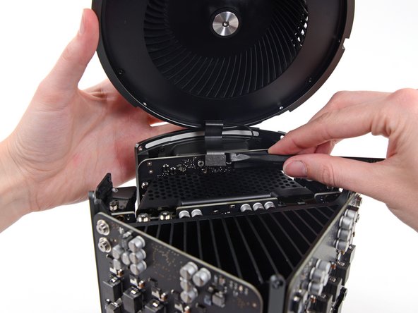
    • ファンアセンブリを片手で支えながら、ファンケーブルのブラケットに留められたT8非脱落型ネジを緩めます。

    • これらのネジはMac Proに固定されています。取り出そうとしないでください。

    On my Mac Pro (assembled mid-2017) these are T8 screws. In fact, there were no T7 screws anywhere in my machine.

    mark33 - 返信

    There was no bracket on top of the cable at all, so I got a bit confused, so I had to skip step 5 and 6.

    Rakesh - 返信

    On my machine, a TR7 worked to remove them due to the weird angle.

    Wilson Gaberino - 返信

  6. Mac Pro Late 2013 ロジックボードの交換: 手順 6、 1の画像 1
    • ピンセットを使って、ファンアセンブリからファンケーブルブラケットを引き出します。

  7. Mac Pro Late 2013 ロジックボードの交換: 手順 7、 2の画像 1 Mac Pro Late 2013 ロジックボードの交換: 手順 7、 2の画像 2
    • スパッジャーの平面側先端を使って、ファンアセンブリのリボンケーブルをIOボードから接続を外します。

  8. Mac Pro Late 2013 ロジックボードの交換: 手順 8、 1の画像 1
    • IOボードからファンアセンブリのアンテナケーブルの接続を外します。

    • Mac Proからファンアセンブリを取り外します。

    You don't have to remove the fan assy to do the steps below. They can be done with the fan assy still attached.

    Fat Mango - 返信

  9. Mac Pro Late 2013 ロジックボードの交換, 下部ケース: 手順 9、 3の画像 1 Mac Pro Late 2013 ロジックボードの交換, 下部ケース: 手順 9、 3の画像 2 Mac Pro Late 2013 ロジックボードの交換, 下部ケース: 手順 9、 3の画像 3
    • Mac Proを180度裏返します。

    • 下部ケースの外周に留められた5.1 mm T10トルクスネジを5本外します。

  10. Mac Pro Late 2013 ロジックボードの交換: 手順 10、 2の画像 1 Mac Pro Late 2013 ロジックボードの交換: 手順 10、 2の画像 2
    • 下部ケースを注意深く持ち上げて、Mac Proから外します。

  11. Mac Pro Late 2013 ロジックボードの交換, インターコネクトボード: 手順 11、 2の画像 1 Mac Pro Late 2013 ロジックボードの交換, インターコネクトボード: 手順 11、 2の画像 2
    • スパッジャーの平面側先端を使って、グラフィックカードのデータコネクションの片側をゆっくりと捻って外します。

  12. Mac Pro Late 2013 ロジックボードの交換: 手順 12、 3の画像 1 Mac Pro Late 2013 ロジックボードの交換: 手順 12、 3の画像 2 Mac Pro Late 2013 ロジックボードの交換: 手順 12、 3の画像 3
    • 慎重に反対側も外します。

    • コネクタを裏返し、グラフィックカードの邪魔にならないようにします。

    • 他のグラフィックカードにも、この手順を繰り返します。

  13. Mac Pro Late 2013 ロジックボードの交換: 手順 13、 1の画像 1
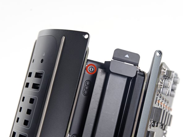
    • インターコネクトボードをヒートシンクに固定している6.0 mm T8トルクスネジを2本外します。

    These are actually 6.0mm T8 Torx Screws. 12/07/2016.

    Todd - 返信

    Ended up being T9 screws for me.

    Nathaniel Wilson - 返信

    On my Mac Pro (assembled mid-2017) these are T8 screws. In fact, there were no T7 screws anywhere in my machine.

    mark33 - 返信

    These are T8 screws in my 2013 Mac Pro.

    Sangers - 返信

    T8 screws for me, i did and edit to this step

    Steve McGinn - 返信

    Ended up being T15 screws on my machine

    Spencer Curtis - 返信

  14. Mac Pro Late 2013 ロジックボードの交換: 手順 14、 3の画像 1 Mac Pro Late 2013 ロジックボードの交換: 手順 14、 3の画像 2 Mac Pro Late 2013 ロジックボードの交換: 手順 14、 3の画像 3
    • インターコネクトボードをロジックボードのスロットコネクションから少しずつ引き上げます。

    • まず片側を外してから、反対側を外すことをお勧めします。

    • Mac Proからインターコネクトボードを完全に外さないでください。IOボードが接続されたままです。

  15. Mac Pro Late 2013 ロジックボードの交換: 手順 15、 2の画像 1 Mac Pro Late 2013 ロジックボードの交換: 手順 15、 2の画像 2
    • インターコネクトボードを上下に反転させて、IOボードデータケーブルを露出させます。

    • スパッジャーの平面側先端を使って、同じように捻って、IOボードのデータケーブルの片側を分離します。

  16. Mac Pro Late 2013 ロジックボードの交換: 手順 16、 2の画像 1 Mac Pro Late 2013 ロジックボードの交換: 手順 16、 2の画像 2
    • スパッジャーの平面側先端を使って、IOボードデータケーブルの反対側を外します。

    • ケーブルが作業の邪魔にならないよう折り曲げて、Mac Proからインターコネクトケーブルを取り出します。

  17. Mac Pro Late 2013 ロジックボードの交換, 電源ユニット: 手順 17、 1の画像 1
    • Mac Proを裏返して、水平な表面上にゆっくりと載せます。

    • 画像のように、ヒートシンクの角と相互接続ボードに取り付ける2本のスタンドオフネジの支柱にMac Proを寝かせることをお勧めします。

  18. Mac Pro Late 2013 ロジックボードの交換: 手順 18、 2の画像 1 Mac Pro Late 2013 ロジックボードの交換: 手順 18、 2の画像 2
    • 電源ユニットケージ(両側に一つづつ)の側面から、3.6 mm T5トルクスネジを2本外します。

    those are t4 screws in my mac

    Andrzej Kiryluk - 返信

    T4s on mine, as well

    rwcinmsp - 返信

  19. Mac Pro Late 2013 ロジックボードの交換: 手順 19、 1の画像 1
    • 電源ユニットの上部から電源ユニットケージを外します。

    • このケージを取り外すと、電源の内部部品が露出します。電源の部品や回路に触れないように十分注意してください。

    • 電源の中にネジや工具を落とすと、電源が破損することがありますのでご注意ください。

  20. Mac Pro Late 2013 ロジックボードの交換: 手順 20、 1の画像 1
    • Mac Proに電源ユニットアセンブリを固定している、 5.5 mm T8トルクスネジを4本外します。

  21. Mac Pro Late 2013 ロジックボードの交換: 手順 21、 1の画像 1
    • Mac Proから電源ユニットアセンブリを外します。

  22. Mac Pro Late 2013 ロジックボードの交換, ロジックボード: 手順 22、 1の画像 1
    • 5.5 mm T8トルクスネジを2本外します。

    Il est possible de les retirer aussi des le début une fois le “fond” rond du Mac pro retiré

    Chris - 返信

    Step 22 when reassembling, it helps not to fully tighten until you put the screws in from step 20.

    Mike Sheedy - 返信

  23. Mac Pro Late 2013 ロジックボードの交換: 手順 23、 1の画像 1
    • CPUヒートシンクブラケットから12.8 mm T10トルクスネジを4本外します。

    • 8本あるネジのうち外側の4本のみ外します。

    I cannot unscrew one of those because I appears that one of the elements in wich it is screwd underneath is loose and moving along with the screw, making this operation impossible. Anyone had this issue ?? Any solution ??

    benjaminmonnoyeur - 返信

    I had the same problem. These screws go into threaded inserts, which in turn are screwed into the heatsink. Both have threadlocker compound applied. So the threaded insert’s threadlocker gives up first, and the threaded insert unscrews from the heatsink. Remove all 4 screws, then with a pair of needle nose pliers, hemostat, or thin 7mm wrench, hold the insert steady and unscrew the screw from it.

    Chuck Fry - 返信

    Could I remove these screws and re-screw? I worry that remove them but I can’t re-use them?

    timmy123 -

    I had that problem, too, and I did it like Chuck Fry, with a thin wrench. Unfortunately one threaded insert was so tight that I slipped and a capacitor broke off. Can someone tell me what kind of capacitor I need? I can't find anything under the name listed above the capacitor. Thank you.

    Steph - 返信

    A way to avoid this situation is to ease the tension on the spring slowly and rotate the loosening of four screws a few turns at a time – when the tension is released equally the threaded inserts are more likely to stay in place.

    Steve Esser - 返信

    I had 2 of those double sided screws stuck like that. I carefully removed them from the motherboard using a small vice grip to hold one side, and a torx on the other. Then reinstalled them using locktite compound. Make sure the heat sink is flush to the motherboard in the same way that you found it, or the assembly will not fit back in the case correctly, indicating the CPU may not be securely attached. The result may be that you think you killed your mac when you turn in on again and just hear the fan spinning like crazy but no chime or boot sequence. If that happens, go back in, reset the double sided screws, and make sure the heatsink is flush. Worked for me.

    Sili_pepper - 返信

  24. Mac Pro Late 2013 ロジックボードの交換: 手順 24、 2の画像 1 Mac Pro Late 2013 ロジックボードの交換: 手順 24、 2の画像 2
    • この時点で、ロジックボードは放熱グリスによってヒートシンク上に固定されています。

    • スパッジャーを使って、ヒートシンクからロジックボードをゆっくりと乖離します。

    • ロジックボードを曲げたり破損しないようにご注意ください。

    • ヒートシンクからロジックボードを取り出します。

  25. Mac Pro Late 2013 ロジックボードの交換: 手順 25、 2の画像 1 Mac Pro Late 2013 ロジックボードの交換: 手順 25、 2の画像 2
    • CPUのヒートシンクブラケットから長さ12.8 mm T10トルクスネジを4本外します。

    • CPUヒートシンクブラケットを取り出します。

    On my Mac Pro (assembled mid-2017) these screws are covered with a black sticker presumably to indicate tampering. If you did not know they were screws it would not be obvious. You have to just put the T10 driver right in the center and start turning; it quickly breaks through the sticker.

    mark33 - 返信

    Oh man. Thanks so much for that comment! I would have tried to use pliers!

    Trevor Standley - 返信

    Also remember to support the CPU (On the other side) while removing these screws. Mine CPU fell out from the other side while loosening.

    Daniel Wood - 返信

    On my MacPro there are no screws here. On the backside the place where the back of the screws should be are covered with stickers, but removing the stickers simply reveals a rivet. There’s no screw and seemingly no way to remove the CPU.

    rsproductions - 返信

    Je confirme, un sceau plastique noir protège les 4 vis. Il faut percer et dévisser au centre avec t9 pour moi

    Chris - 返信

    Wow, glad I clicked comments. I had no clue about the sticker. I was about to use some kind of something to get them out 😂

    Marc Kinnear - 返信

  26. Mac Pro Late 2013 ロジックボードの交換: 手順 26、 1の画像 1
    • 2つ目のヒートシンクブラケットを取り外します。

  27. Mac Pro Late 2013 ロジックボードの交換: 手順 27、 2の画像 1 Mac Pro Late 2013 ロジックボードの交換: 手順 27、 2の画像 2
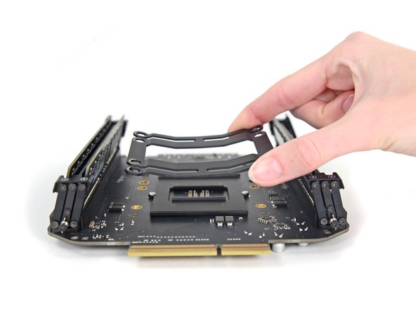
    • CPUとブラケットからロジックボードを持ち上げて取り出します。

    • 再組み立ての際は、CPU上の放熱グリスを綺麗に除去してから交換します。

    • 放熱グリスを簡単に交換できるガイドも準備しています。

    There is one import piece of information when replacing or upgrading these processors. There are two possible orientations and only one is correct (correct me if I’m wrong!). There’s a small arrow on one corner of the processor that needs to be aligned to the correct side. Just match the orientation of the original processor - this can be difficult or easy to overlook since the tiny alignment arrow is usually covered with thermal paste. Clean the Thermal paste off the old processor before you remove it to see the correct alignment.

    Steve Esser - 返信

終わりに

デバイスを再組み立てする際は、これらの手順を逆の順番に従って作業を進めてください。

11 の人々がこのガイドを完成させました。

以下の翻訳者の皆さんにお礼を申し上げます:

en jp

90%

これらの翻訳者の方々は世界を修理する私たちのサポートをしてくれています。 あなたも貢献してみませんか?
翻訳を始める ›

作成者

1人の作成者と共同作成されました。

Andrew Optimus Goldheart

メンバー登録日: 10/17/09

502,810 ポイント

407のガイドは作成済み

チーム

iFixit iFixit人のメンバー

Staff

135 メンバー

16,817のガイドは作成済み

コメント 1 件

The RAM/CPU board is only attached to the thermal core around the processor area. This means seating RAM modules can flex the board (which has no support under the RAM sockets) so take extra care seating RAM modules.

john gilchrist - 返信

コメントを追加

統計データ:

過去 24時間: 1

過去 7 日: 20

過去 30 日: 110

今までの合計 15,134