はじめに
IOボードは、Mac Proのすべてのポート(Thunderbolt、USB、3.5 mmスピーカーおよびヘッドフォンジャック、イーサネットポート、HDMI)をホストしています。 IOボードを交換するには、このガイドを使用してください。
Mac Proで作業を始める前に :コンピュータのプラグを抜き、電源ボタンを10秒間押し続けて、電源のコンデンサを放電します。
ご注意くださいコンデンサのリードまたは電源の背面にある露出したはんだ接合部には、絶対に触れないでください。 ボードの端のみを扱ってください。
必要な工具と部品
-
-
5.1 mmT10トルクスネジをファンアセンブリアウターケースから外します。
Fat Mango is correct. That said. If you do pull the fan assembly note that the screws are all held in with blue Permatex and breaking them free takes a fair amount of effort. Getting a good set of Torx screwdrivers is a must.
Jim WIlson - 返信
Hey guys, what would happen if you only replace one card.. I have a D300 but the plan is to upgrade to D500 or D600. So If I can afford and install one instead of the pair would it increase something? or will it cause any conflict? I guess I don’t understand if I the Mac Pro has 2 D300 graphic cards that means each has 1GB? Same as If I would Install 1 D600 that would increase 3GB only? Thanks.
D300 = 2GB each card. Very few apps uses two cards at the same time.
Gio Cas -
The (5) Screws are Apple part number 923-0713
-
-
-
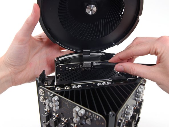
ファンアセンブリを片手で支えながら、ファンケーブルのブラケットに留められたT8非脱落型ネジを緩めます。
On my machine, a TR7 worked to remove them due to the weird angle.
-
-
-
-
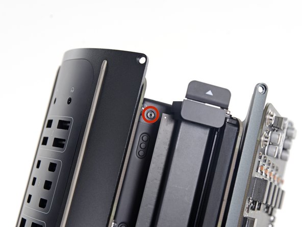
インターコネクトボードをヒートシンクに固定している6.0 mm T8トルクスネジを2本外します。
Ended up being T9 screws for me.
T8 screws for me, i did and edit to this step
Ended up being T15 screws on my machine
-
-
-
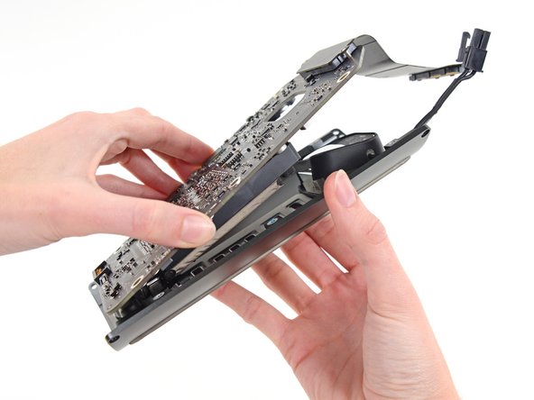
スパッジャーの平面側先端を使い、電源のDC-OutコネクタをIOボードのソケットから外します。
-
スパッジャーの先端を使って、IOボードのソケットから電源データケーブルを外します。
Need to add T9 Torx Screwdriver to list of tools at the beginning of this article.
-
-
-
電源ユニットの側面から、長さ9.0 mmシルバーのT10トルクスネジを4本外します。
-
-
-
IOボードをIOシールドに固定しているシルバーの9mm T10トルクスネジを2本外します。
On reassembly, before tightening these 2 9.0mm T10s, make sure the other 4 holes line up. Otherwise you might be setting yourself up for cross threading the 4 remaining 9.0 mm T10 that are already in a bad spot for torquing.
Might not be a bad idea to put the other 4 halfway in to be sure no resistance, then tighten the 2 in this step, then remove the other 4.
-
-
-
スパッジャーの先端を使って、IOシールドリボンケーブルのZIFコネクタ上の固定フラップを跳ね上げます。
-
IOシールドリボンケーブルの接続を外します。
-
-
-
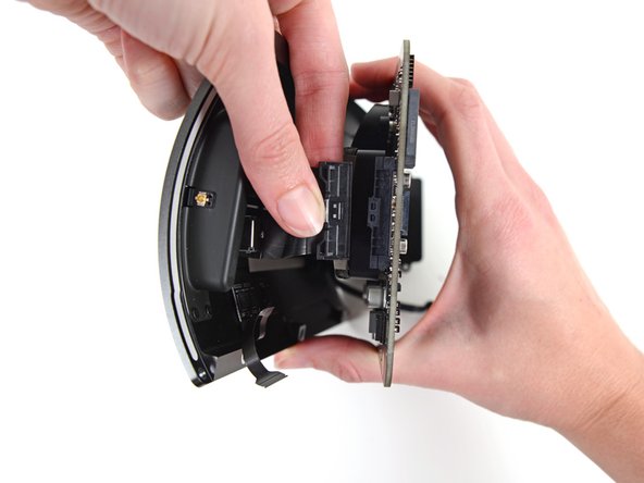
IO ボードからオーディオジャックリボンケーブルのコネクタを摘んで引き抜きます。
-


デバイスを再組み立てする際は、これらの手順を逆の順番に従って作業を進めてください。
デバイスを再組み立てする際は、これらの手順を逆の順番に従って作業を進めてください。
5 の人々がこのガイドを完成させました。
以下の翻訳者の皆さんにお礼を申し上げます:
100%

これらの翻訳者の方々は世界を修理する私たちのサポートをしてくれています。 あなたも貢献してみませんか?
翻訳を始める ›

3 件のコメント
How do you even get the a t10 to fit a such an aggressive angle?
My USB ports don’t work.. I replaced this board and they still don’t work.. Suggestions as to what could be causing this?
I’m having a severe problem with the data cable the runs from the power supply to the IO board. First, I broke a couple of the pins, so I had to order a new IO board. Now the pins are slightly different. Before, they were just sitting out unprotected, but the new board I purchased has a type of barrier around it, but my data cable won’t fit onto the pins now with the new protective barriers. Please help!