メインコンテンツにスキップ

Mac Mini Late 2014 Logic Board Assembly Replacement

必要条件のみ
この修理ガイドは、他のガイドの前提条件として使用されます。それ自体は不完全で、単独で使用されることはありません。

必要な工具と部品

  1. Mac Mini Late 2014 Logic Board Assembly Replacement, Logic Board Assembly: 手順 1、 1の画像 1
    • Remove the 2.6 mm T6 screw securing the SATA cable connector bracket.

  2. Mac Mini Late 2014 Logic Board Assembly Replacement: 手順 2、 2の画像 1 Mac Mini Late 2014 Logic Board Assembly Replacement: 手順 2、 2の画像 2
    • Remove the SATA cable connector bracket.

  3. Mac Mini Late 2014 Logic Board Assembly Replacement: 手順 3、 2の画像 1 Mac Mini Late 2014 Logic Board Assembly Replacement: 手順 3、 2の画像 2
    • Use the flat end of a spudger to lift the SATA cable connector up off of its socket on the logic board.

  4. Mac Mini Late 2014 Logic Board Assembly Replacement: 手順 4、 2の画像 1 Mac Mini Late 2014 Logic Board Assembly Replacement: 手順 4、 2の画像 2
    • Use the tip of a spudger to disconnect the IR sensor cable connector by prying it straight up from its socket.

  5. Mac Mini Late 2014 Logic Board Assembly Replacement: 手順 5、 1の画像 1
    • The following three steps only apply to Mac minis equipped with a PCIe SSD. Skip the next three steps if your Mac mini only has a hard drive.

    • Remove the two 2.6 mm T6 screws securing the PCIe SSD cable bracket.

  6. Mac Mini Late 2014 Logic Board Assembly Replacement: 手順 6、 2の画像 1 Mac Mini Late 2014 Logic Board Assembly Replacement: 手順 6、 2の画像 2
    • Remove the PCIe SSD cable bracket.

  7. Mac Mini Late 2014 Logic Board Assembly Replacement: 手順 7、 2の画像 1 Mac Mini Late 2014 Logic Board Assembly Replacement: 手順 7、 2の画像 2
    • Lift the PCIe SSD connector up off its socket.

  8. Mac Mini Late 2014 Logic Board Assembly Replacement: 手順 8、 1の画像 1
    • Remove the single 16 mm T6 screw securing the logic board.

  9. Mac Mini Late 2014 Logic Board Assembly Replacement: 手順 9、 1の画像 1
    この手順で使用する道具:
    Mac mini Logic Board Removal Tool
    $4.99
    購入する
    • To remove the logic board, the two cylindrical rods of the Mac mini Logic Board Removal Tool must be inserted into the holes highlighted in red. Inserting instruments into any logic board holes other than the ones highlighted in red may destroy the logic board.

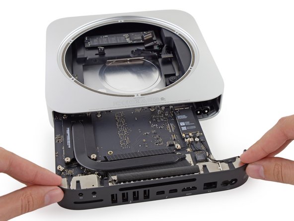
    • Insert the Mac mini Logic Board Removal Tool into the two holes highlighted in red. Be sure the rods make contact with the case under the logic board before proceeding.

  10. Mac Mini Late 2014 Logic Board Assembly Replacement: 手順 10、 3の画像 1 Mac Mini Late 2014 Logic Board Assembly Replacement: 手順 10、 3の画像 2 Mac Mini Late 2014 Logic Board Assembly Replacement: 手順 10、 3の画像 3
    • Carefully pull the tool toward the I/O board. The logic board and I/O board assembly should slightly slide out of the outer case.

    • Cease prying when the removal tool makes contact with the opening in the rear case.

    • Remove the Mac mini Logic Board Removal tool.

  11. Mac Mini Late 2014 Logic Board Assembly Replacement: 手順 11、 2の画像 1 Mac Mini Late 2014 Logic Board Assembly Replacement: 手順 11、 2の画像 2
    • Pull the DC-In cable connector straight out of its socket on the logic board.

  12. Mac Mini Late 2014 Logic Board Assembly Replacement: 手順 12、 2の画像 1 Mac Mini Late 2014 Logic Board Assembly Replacement: 手順 12、 2の画像 2
    • Carefully slide the logic board assembly out of the Mac mini, minding any cables that may get caught.

終わりに

To reassemble your device, follow these instructions in reverse order.

ある他の人がこのガイドを完成しました。

作成者

3人の作成者と共同で作成されました。

Sam Goldheart

メンバー登録日: 10/18/12

465,777 ポイント

538のガイドは作成済み

チーム

iFixit iFixit人のメンバー

Staff

135 メンバー

16,817のガイドは作成済み

0 件のコメント

コメントを追加

統計データ:

過去 24時間: 0

過去 7 日: 0

過去 30 日: 0

今までの合計 566