はじめに
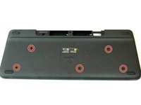
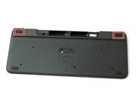
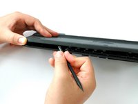
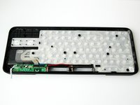
This is a replacement guide for the Logitech Harmony Smart Keyboard's key printed circuit board.
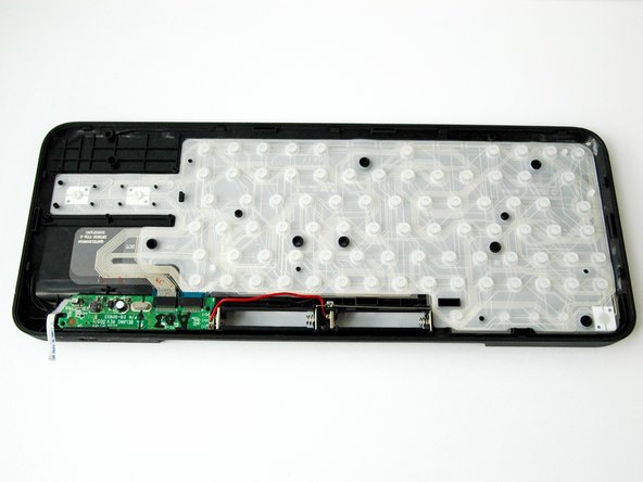
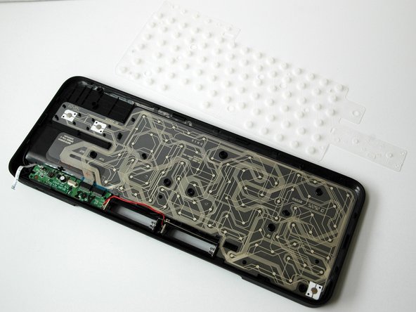
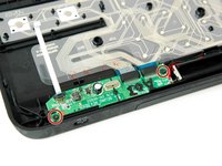
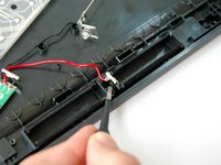
The keyboard printed circuit board (PCB) sends messages to the wifi and transmits key data to the server.
必要な工具と部品
-
-
-
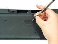
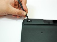
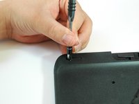
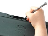
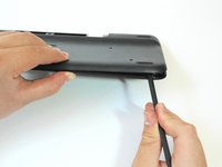
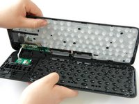
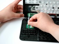
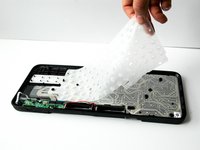
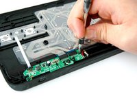
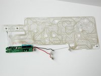
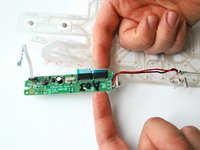
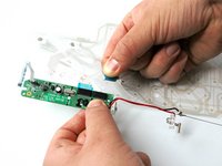
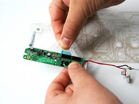
Grip the lower end of the ribbon flex cable (white band) using your thumb and index finger.
-
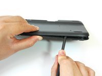
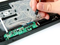
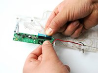
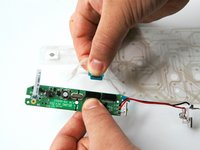
Then slide the strip out toward yourself in a scooping motion.
-


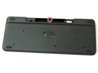


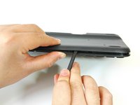


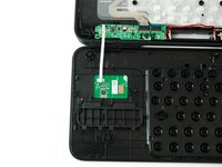
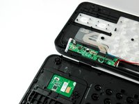

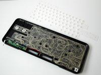


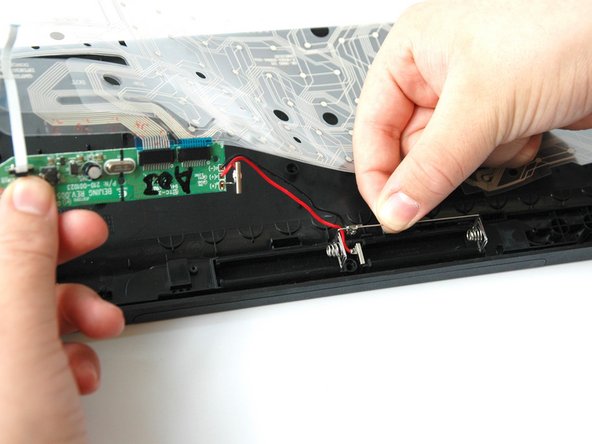


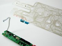
To reassemble your device, follow these instructions in reverse order.
ある他の人がこのガイドを完成しました。
チーム

CSU Fullerton, Team S1-G2, Bruce Fall 2017 CSU Fullerton, Team S1-G2, Bruce Fall 2017人のメンバー
CSUF-BRUCE-F17S1G2
3 メンバー
10のガイドは作成済み
2件のガイドコメント
This is really very informative to read and helpful while replacement or cleaning theprinted circuit board . I really want my friend companies engineer to read this type of information and work on it in practical. i wanna tag that company here as well @XG-technologies (https://xg-pcb.com/). Moreover keep sharing these type of informative blogs. really liked it.
dnde cmprar el recambi, cm se ve n funcina la 0