はじめに
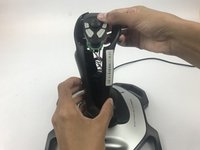
After extended use certain parts may require cleaning or replacement. This guide will assist you in safely disassembling the top handle portion of the joystick.
必要な工具と部品
-
-
Remove these three Phillips #1 screws:
-
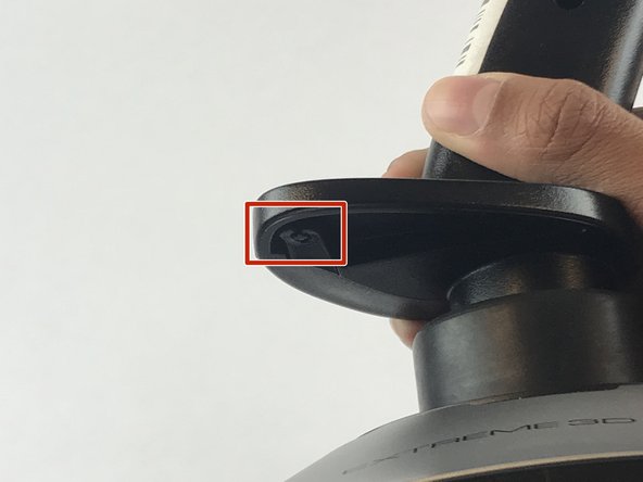
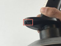
Two 10mm screws.
-
One 7mm screw.
-
-


To reassemble your device, follow these instructions in reverse order.
6 の人々がこのガイドを完成させました。
チーム

USF Tampa, Team S7-G1, Passmore Spring 2018 USF Tampa, Team S7-G1, Passmore Spring 2018人のメンバー
USFT-PASSMORE-S18S7G1
4 メンバー
7のガイドは作成済み
3件のガイドコメント
yeah but i got this far before looking at the site, and what i really want to see is how the cotter ring pin is set on the shaft that enables the z-rot instead of locking it down.
if you havent worked it out already, the Z-rot spring needs spread across a little 3/8 inch tab, otherwise it will lock the axis a few degrees off center
reassembling is tricky. The spring tabs for z-rot need to be aligned on one side of the handle and the z-rot potentiometer needs aligning on the other. There is nothing obvious in the handle design to guide the correct positioning. The difficult part is getting the pot tab to stay in its slot. If anyone knows of a technique to assist getting the handles halves and pot in the correct alignment, please do tell.