はじめに
After the top casing is removed we can remove the bottom casing to isolate the motherboard.
必要な工具と部品
-
-
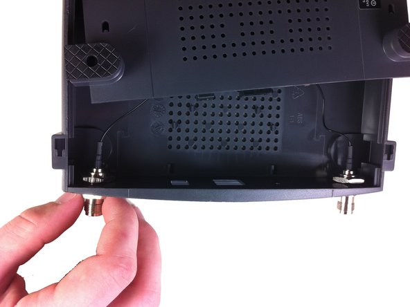
Remove the antennas from the back of the device. To do this, follow steps 1 and 2 of Installing the Antennas Guide: Linksys WAP54g Antennas Replacement
-
-
-
-
Unscrew the two screws that connect the motherboard to the bottom casing.
-


After the motherboard is isolated component level repairs can be made.
After the motherboard is isolated component level repairs can be made.
2 の人々がこのガイドを完成させました。
チーム

Cal Poly, Team 21-21, Maness Fall 2011 Cal Poly, Team 21-21, Maness Fall 2011人のメンバー
CPSU-MANESS-F11S21G21
5 メンバー
12のガイドは作成済み