メインコンテンツにスキップ

このバージョンは誤った内容を含んでいる可能性があります。最新の承認済みスナップショットに切り替えてください。

必要な工具と部品

  1. この手順は未翻訳です。 翻訳を手伝う。

    : 手順 1、 1の画像 1
    • Ensure the device is off and unplugged.

    • Remove the stylus from its port and set aside.

  2. この手順は未翻訳です。 翻訳を手伝う。

    : 手順 2、 2の画像 1 : 手順 2、 2の画像 2
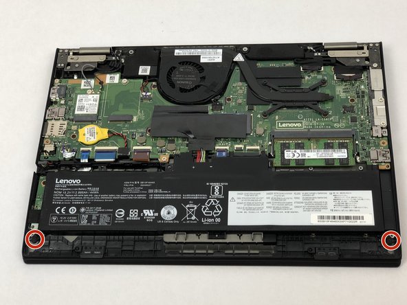
    • Using a Phillips #1 screwdriver, gently unscrew the eight 1.3 mm Phillips #1 screws until you hear an audible click.

    • The screws will not separate from the bottom cover when loose.

  3. この手順は未翻訳です。 翻訳を手伝う。

    : 手順 3、 2の画像 1 : 手順 3、 2の画像 2
    • The bottom cover is attached via several plastic clips located around the edges of the bottom cover.

    • Using a plastic opening tool, gently pry the bottom cover from the laptop.

    • Work the plastic opening tool around the edges of the bottom cover undoing all of the plastic clips, as shown in the picture.

  4. この手順は未翻訳です。 翻訳を手伝う。

    : 手順 4、 2の画像 1 : 手順 4、 2の画像 2
    • Place your fingers around the edges of the cover and remove it.

  5. この手順は未翻訳です。 翻訳を手伝う。

    : 手順 5、 3の画像 1 : 手順 5、 3の画像 2 : 手順 5、 3の画像 3
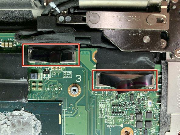
    • Fold back the plastic cover to access the battery connection.

    • Remove the battery connection using your two index fingers.

    • Gently separate the connectors.

  6. この手順は未翻訳です。 翻訳を手伝う。

    : 手順 6、 3の画像 1 : 手順 6、 3の画像 2 : 手順 6、 3の画像 3
    • Unscrew the two 1.3 mm Phillips #1 fasteners using a Phillips #1 screwdriver and set them aside.

    • Lift the battery free from its mounting and remove it.

  7. この手順は未翻訳です。 翻訳を手伝う。

    : 手順 7、 2の画像 1 : 手順 7、 2の画像 2
    • Using both thumbs, pinch the RAM's mounting clips outward.

    • The RAM module will spring up on its own.

  8. この手順は未翻訳です。 翻訳を手伝う。

    : 手順 8、 1の画像 1
    • Gently remove it from its mounting.

  9. この手順は未翻訳です。 翻訳を手伝う。

    : 手順 9、 2の画像 1 : 手順 9、 2の画像 2
    • Heatsink should be cool to the touch.

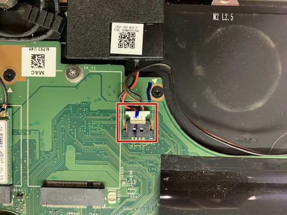
    • Using your index fingers, gently remove the fan’s power connection.

  10. この手順は未翻訳です。 翻訳を手伝う。

    : 手順 10、 2の画像 1 : 手順 10、 2の画像 2
    • Using a Phillips #1 screwdriver, remove the four 1.3 mm Phillips #1 screws and set them aside.

    • The screws will not separate from the mounting when loose.

  11. この手順は未翻訳です。 翻訳を手伝う。

    : 手順 11、 1の画像 1
    • Using your index finger and thumb, gently pry the cooler from its mountings and remove the assembly.

  12. この手順は未翻訳です。 翻訳を手伝う。

    : 手順 12、 3の画像 1 : 手順 12、 3の画像 2 : 手順 12、 3の画像 3
    • Using a Phillips #1 screwdriver, remove the 1.3 mm screw and set it aside.

  13. この手順は未翻訳です。 翻訳を手伝う。

    : 手順 13、 2の画像 1 : 手順 13、 2の画像 2
    • Carefully pull out the Wi-Fi card.

    • Be sure to pull laterally, not upwards.

  14. この手順は未翻訳です。 翻訳を手伝う。

    : 手順 14、 2の画像 1 : 手順 14、 2の画像 2
    • Carefully disconnect the 2 cables from the WiFi-Card as indicated on the card label.

    • Set the Wifi-Card aside.

  15. この手順は未翻訳です。 翻訳を手伝う。

    : 手順 15、 2の画像 1 : 手順 15、 2の画像 2
    • Disconnect the speaker cable located near hinge side of the laptop.

    • Remove both speakers from the assembly.

  16. この手順は未翻訳です。 翻訳を手伝う。

    : 手順 16、 3の画像 1 : 手順 16、 3の画像 2 : 手順 16、 3の画像 3
    • Gently lift up the SD chip's black protective film.

    • Using a Phillips #1 screwdriver, remove the 1.3 mm screw and set it aside.

    • Unplug the SD chip from the assembly and set the SD chip aside.

  17. この手順は未翻訳です。 翻訳を手伝う。

    : 手順 17、 3の画像 1 : 手順 17、 3の画像 2 : 手順 17、 3の画像 3
    • Pull up on the 2 black tabs to remove the cords located along the hinge edge of the device.

  18. この手順は未翻訳です。 翻訳を手伝う。

    : 手順 18、 3の画像 1 : 手順 18、 3の画像 2 : 手順 18、 3の画像 3
    • Pull up the 6 colored tabs along the edge of the motherboard to disconnect them from the motherboard.

  19. この手順は未翻訳です。 翻訳を手伝う。

    : 手順 19、 1の画像 1
    • Remove the fourteen .8 mm screws on the motherboard using a Phillips #00 screwdriver.

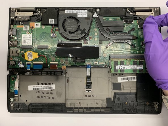
    • Carefully lift the motherboard out of assembly.

    • Ensure no wires or cables remain connected.

ゴール

5 の人々がこのガイドを完成させました。

作成者

3人の作成者と共同で作成されました。

Ian Jenkins

メンバー登録日: 02/18/20

241 ポイント

1ガイドが承認済み

0 件のコメント

コメントを追加

統計データ:

過去 24時間: 2

過去 7 日: 10

過去 30 日: 37

今までの合計 2,205