メインコンテンツにスキップ

このバージョンは誤った内容を含んでいる可能性があります。最新の承認済みスナップショットに切り替えてください。

必要な工具と部品

  1. この手順は未翻訳です。 翻訳を手伝う。

    : 手順 1、 1の画像 1
    • There is no external access to the battery. Please make sure the at the battery has been drained or disabled through BIOS before beginning.

    • Flip the device over.

  2. この手順は未翻訳です。 翻訳を手伝う。

    : 手順 2、 1の画像 1
    • Use a Phillips #00 screwdriver to remove one M2 x 3mm screw from the side of the device.

  3. この手順は未翻訳です。 翻訳を手伝う。

    : 手順 3、 3の画像 1 : 手順 3、 3の画像 2 : 手順 3、 3の画像 3
    • Swing the cover out slightly like a hinge.

    • Pull the cover directly away from the case towards the base of the laptop.

    • Lift the cover up and away from the device to remove it.

    • You may hear a slight pop when you pull the cover off.

  4. この手順は未翻訳です。 翻訳を手伝う。

    : 手順 4、 1の画像 1
    • Use the clear tab to slide the hard drive out of the device.

  5. この手順は未翻訳です。 翻訳を手伝う。

    : 手順 5、 3の画像 1 : 手順 5、 3の画像 2 : 手順 5、 3の画像 3
    • To replace the hard drive, remove the four M2 × 4mm wafer-headed screws on the sides of the hard drive case using a Phillips #00 screwdriver.

    • Slide the old hard drive directly out.

    • When reassembling, make sure the hard drive is securely in the case before beginning.

  6. この手順は未翻訳です。 翻訳を手伝う。

    : 手順 6、 2の画像 1 : 手順 6、 2の画像 2
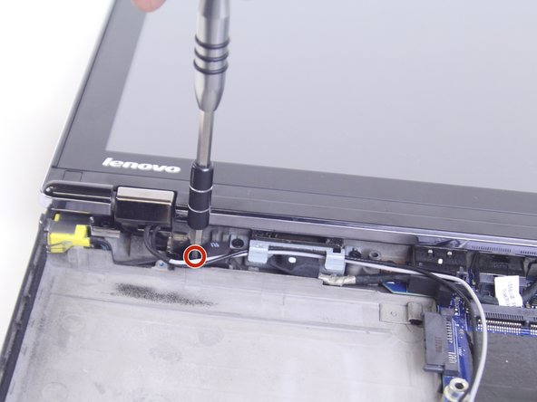
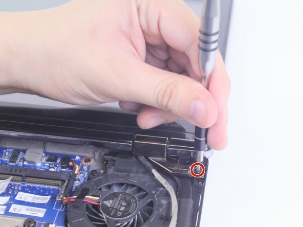
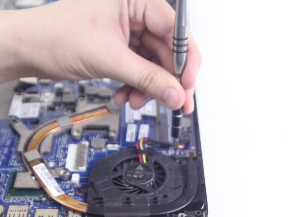
    • Use a Phillips #0 screwdriver to remove eight M2 × 3 mm screws near the front opening and scattered across the bottom of the laptop.

    • Remove three M2x3 mm screws using a Phillips #00 screwdriver from the base of the laptop near the opening.

  7. この手順は未翻訳です。 翻訳を手伝う。

    : 手順 7、 1の画像 1
    • Remove the M3 x 2mm screw from the hole left by the hard drive using a Phillips #00 screwdriver.

  8. この手順は未翻訳です。 翻訳を手伝う。

    : 手順 8、 2の画像 1 : 手順 8、 2の画像 2
    • Flip over the device.

    • Open the device normally.

  9. この手順は未翻訳です。 翻訳を手伝う。

    : 手順 9、 1の画像 1
    • Wedge the plastic opening tool between the upper and lower halves of the lower case.

    • Lift the end of the opening tool slowly until the case separates.

    • Hearing a small popping or cracking noise during this step is normal

  10. この手順は未翻訳です。 翻訳を手伝う。

    : 手順 10、 1の画像 1
    • Lift the upper half of the case up slowly.

    • Be sure not to yank any of the wires connected to the case as this could damage them.

  11. この手順は未翻訳です。 翻訳を手伝う。

    : 手順 11、 3の画像 1 : 手順 11、 3の画像 2 : 手順 11、 3の画像 3
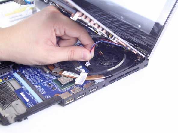
    • Locate and disconnect the 4 ribbon wires from the top case.

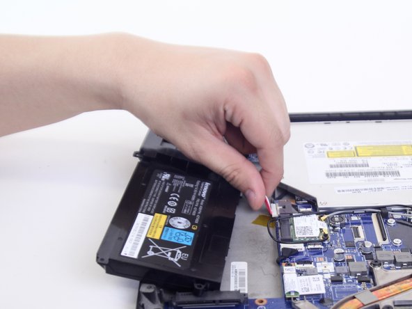
    • Locate and disconnect the two additional connecting wires.

    • Some wires may be connected by a clamp. In order to remove the clamp, press upwards on the lever attached to the connector

    • Be careful to not yank on the wires when disconnecting them as they are easily damaged.

  12. この手順は未翻訳です。 翻訳を手伝う。

    : 手順 12、 1の画像 1
    • Lift the unattached case away from the device and place it to the side.

    • When reassembling ensure that all parts of the case are properly aligned.

  13. この手順は未翻訳です。 翻訳を手伝う。

    : 手順 13、 2の画像 1 : 手順 13、 2の画像 2
    • Disconnect the cable connecting the battery and the motherboard

  14. この手順は未翻訳です。 翻訳を手伝う。

    : 手順 14、 2の画像 1 : 手順 14、 2の画像 2
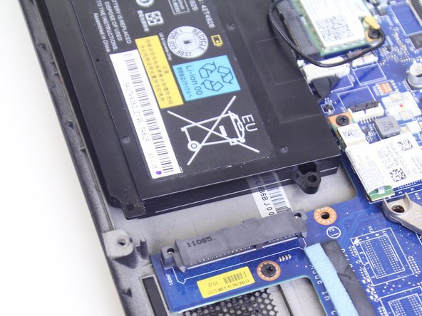
    • Lift the battery out of the case.

    • The battery is secured by grey plastic tubes passing through the case. To place the battery back in, line up the openings on the battery with the tubes.

  15. この手順は未翻訳です。 翻訳を手伝う。

    : 手順 15、 2の画像 1 : 手順 15、 2の画像 2
    • Remove the two M2 x 3mm securing the the optical drive to the device using a Phillips #000 screwdriver.

  16. この手順は未翻訳です。 翻訳を手伝う。

    : 手順 16、 1の画像 1
    • Slide the optical drive away from the motherboard in order to remove it.

  17. この手順は未翻訳です。 翻訳を手伝う。

    : 手順 17、 2の画像 1 : 手順 17、 2の画像 2
    • Unscrew the two M2 x 3mm screws near the hinges using a Phillips #00 screwdriver.

  18. この手順は未翻訳です。 翻訳を手伝う。

    : 手順 18、 3の画像 1 : 手順 18、 3の画像 2 : 手順 18、 3の画像 3
    • Slide the black and grey wires out from underneath the plastic tab with the plastic opening tool.

    • Disconnect the black and grey wires connecting the screen and the motherboard.

  19. この手順は未翻訳です。 翻訳を手伝う。

    : 手順 19、 1の画像 1
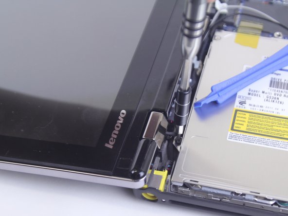
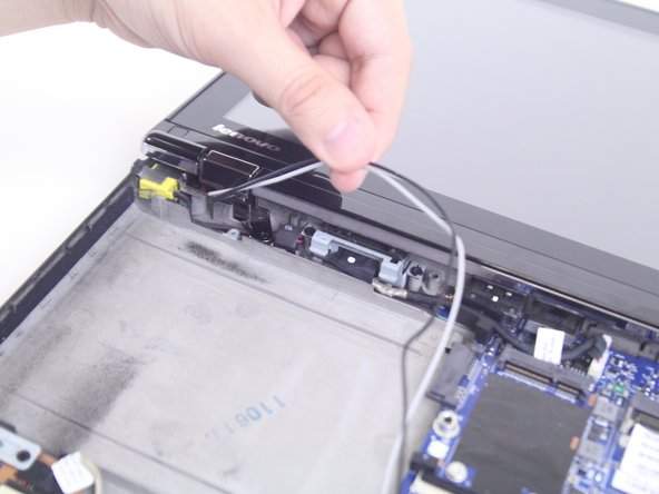
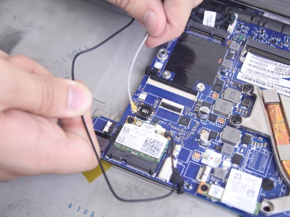
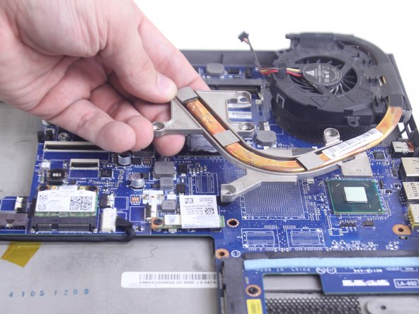
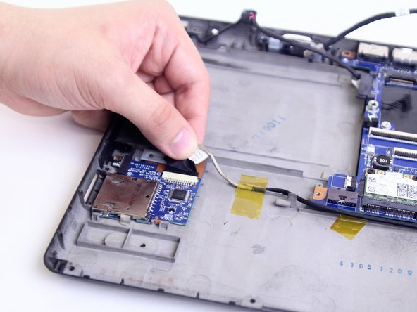
    • Pull out the fabric covered wire connecting the Screen to the motherboard underneath the cooling fan.

    • Make sure to pull parallel to the slot the wire is connected to, otherwise you may damage or completely break it.

  20. この手順は未翻訳です。 翻訳を手伝う。

    : 手順 20、 1の画像 1
    • Lift the screen away from the device.

  21. この手順は未翻訳です。 翻訳を手伝う。

    : 手順 21、 1の画像 1
    • Use a Phillips #0 screwdriver to remove the four M2 x 6mm screws connecting the heatsink to the motherboard.

  22. この手順は未翻訳です。 翻訳を手伝う。

    : 手順 22、 2の画像 1 : 手順 22、 2の画像 2
    • Use a Phillips #00 screwdriver to remove the two M2 x 3mm screws from the fan.

  23. この手順は未翻訳です。 翻訳を手伝う。

    : 手順 23、 2の画像 1 : 手順 23、 2の画像 2
    • Disconnect the cable connecting the fan to the motherboard, then remove the fan and the attached fan component from the case.

  24. この手順は未翻訳です。 翻訳を手伝う。

    : 手順 24、 1の画像 1
    • Use a Phillips #000 screwdriver to remove three M2 x 2mm screws from the sides of the motherboard.

  25. この手順は未翻訳です。 翻訳を手伝う。

    : 手順 25、 2の画像 1 : 手順 25、 2の画像 2
    • Disconnect the cable connecting the VGA connector to the motherboard. Then disconnect the cable connecting the card reader to the motherboard.

  26. この手順は未翻訳です。 翻訳を手伝う。

    : 手順 26、 1の画像 1
    • Lift the motherboard from the case and detach the cable from the back of the motherboard connecting to the DC power jack. Remove the motherboard from the case.

ゴール

作成者

2人の作成者と共同で作成されました。

Keyadri Summerlin

メンバー登録日: 10/02/18

1,003 ポイント

7のガイドは作成済み

チーム

Linn Benton Community College, Team S2-G1, Karnes Fall 2018 Linn Benton Community College, Team S2-G1, Karnes Fall 2018人のメンバー

LBCC-KARNES-F18S2G1

3 メンバー

8のガイドは作成済み

0 件のコメント

コメントを追加

統計データ:

過去 24時間: 0

過去 7 日: 3

過去 30 日: 11

今までの合計 649