-
-
With the tablet face down, pull the SD card slot cover out.
-
Using a Phillips #000 screwdriver, remove the 3mm screw located in the SD card slot.
-
-
Insert a plastic opening tool in the small crevasse between the screen and the back panel.
-
Pry the screen away from the back panel.
-
Repeat this on each edge of the device.
-
We found it helpful to leave multiple plastic opening tools wedged in the crevasse to prevent it from closing.
-
This requires heavy force. The back of the device is attached with an adhesive. If the back panel is too hard to remove, use the iOpener.
-
-
After using the plastic opening tools, pry the device open with your hands.
-
Remove the back panel from the screen.
-
![: 手順 4、 2の画像 1]()
![: 手順 4、 2の画像 2]()

この手順で使用する道具:
Magnetic Project Mat
$19.95
購入する
-
-
-
-
-
Using a spudger or a plastic opening tool, disconnect the ribbon cable from the right side of the device.
-
The cable is attached with an adhesive.
-
These images use a metal spudger, which has the potential to damage the device. Use a plastic opening tool or standard spudger instead.
-
-
Using the Phillips #000 screwdriver, remove the two 3mm screws located at the bottom of the ribbon cable.
-
Remove the ribbon cable from the device.
-
-
-
-
-
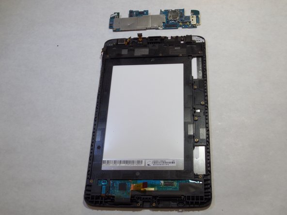
Use a plastic opening tool to lift the motherboard out of the device.
-
These images use a metal spudger, which has the potential to damage the device. Use a plastic opening tool or standard spudger instead.
-
-
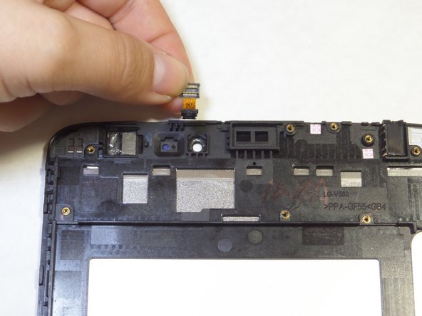
Use a plastic opening tool to lift the front facing camera out of the device.
-
These images use a metal spudger, which has the potential to damage the device. Use a plastic opening tool or standard spudger instead.
このガイドを埋め込む
サイズを選択し、以下のコードをコピーして、このガイドを小さなウィジェットとしてサイト/フォーラムに埋め込みます。
プレビュー