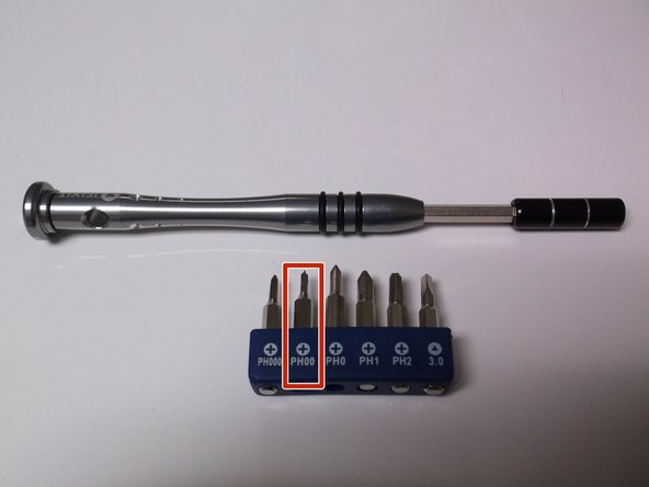
Use a PH00 screwdriver to remove the 6 screws from the mid-frame.
4 screws located around the border of the phone, 2 located around the battery terminal.
Press down and firmly turn screws to prevent slippage. Avoid letting the screw driver slip, as this will result in stripped screws and prevent further progress.
Remove back panel trim.
Use the image when prying to effectively dislodge plastic clips.
The trim piece is extremely delicate, do not use the phone as leverage when prying or plastic will be broken.
Remove back panel, pry in same locations as trim panel in the previous step.
Lift up with pry tool. If you use the phone as leverage, the outer plastic ring will bend and break.
Industrial glue holds this plastic layer, so expect difficulty. Use a second pry tool to cut away glue and assist in removal.
Use tweezers to pull away insulation from speaker, and expose positive and negative terminal points.
Do not remove the white manufacture sticker contrary to what is pictured.
Plug in solder iron, allow 2-4 minutes to come to temperature.
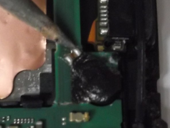
Apply solder iron to each speaker terminal, and melt connection.
When connection is melted, use tweezers to remove defective speaker from the motherboard.
Solder cools quickly, so the connections will solidify without heat.
Avoid dripping, adding, or removing solder to prevent short circuitry.
Insert new speaker into speaker slot.
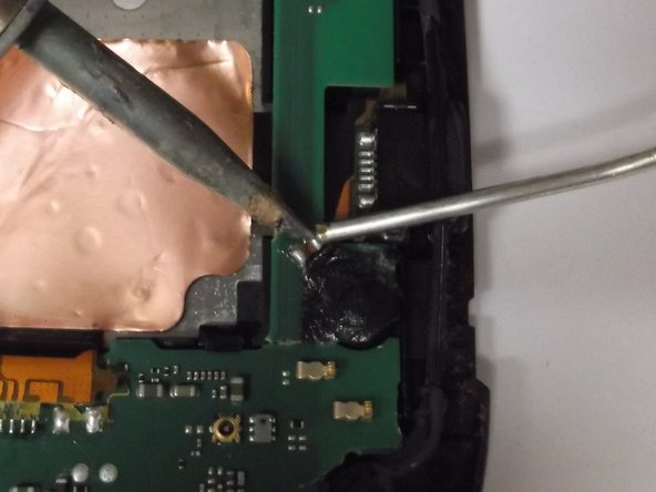
Solder new positive and negative terminals.
Align connection points, apply solder iron to motherboard connection points, then apply solder to heated connection for precise application.
このガイドを埋め込む
サイズを選択し、以下のコードをコピーして、このガイドを小さなウィジェットとしてサイト/フォーラムに埋め込みます。
1つの手順
全ガイド
小サイズ - 600px
中サイズ - 800px
大サイズ - 1200px
プレビュー