メインコンテンツにスキップ

JVC GR-D72U Lateral Function Port Panel Replacement

必要な工具と部品

  1. JVC GR-D72U Lateral Function Port Panel Replacement, Battery: 手順 1、 2の画像 1 JVC GR-D72U Lateral Function Port Panel Replacement, Battery: 手順 1、 2の画像 2
    • Locate button on bottom of camera.

    • Slide button to the right.

  2. JVC GR-D72U Lateral Function Port Panel Replacement: 手順 2、 1の画像 1
    • Pull the battery towards the bottom of the camcorder while lifting battery .

  3. JVC GR-D72U Lateral Function Port Panel Replacement, Lateral Function Port Panel: 手順 3、 3の画像 1 JVC GR-D72U Lateral Function Port Panel Replacement, Lateral Function Port Panel: 手順 3、 3の画像 2 JVC GR-D72U Lateral Function Port Panel Replacement, Lateral Function Port Panel: 手順 3、 3の画像 3
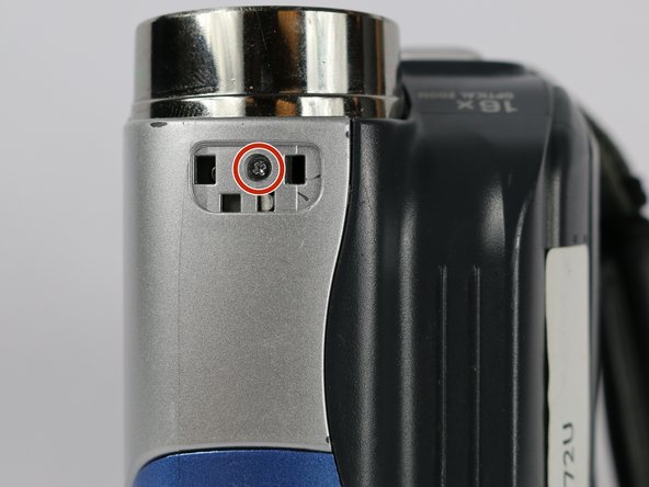
    • Remove silver plate that says “Auto Light” on the top of the camera using a metal spudger.

    • Remove the 3.1 mm screw.

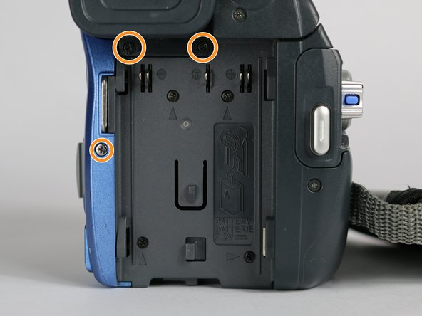
    • Remove the three 5.3 mm screws from the back of the camera.

  4. JVC GR-D72U Lateral Function Port Panel Replacement: 手順 4、 1の画像 1
    • From the bottom of the camera remove the following four screws:

    • 5.3 mm

    • 3.1 mm

    • 5.1 mm

    • 3.5 mm

  5. JVC GR-D72U Lateral Function Port Panel Replacement: 手順 5、 1の画像 1
    • Use the small plastic opening tool to remove the blue side cover piece.

  6. JVC GR-D72U Lateral Function Port Panel Replacement: 手順 6、 1の画像 1
    • Remove the 3.1 mm screw on top of the camera, closest to the LCD monitor.

    • Remove the 5.4 mm screw next to the snapshot button.

  7. JVC GR-D72U Lateral Function Port Panel Replacement: 手順 7、 1の画像 1
    • Remove the 3.1 mm screw next to the USB and DV inputs.

  8. JVC GR-D72U Lateral Function Port Panel Replacement: 手順 8、 1の画像 1
    • Gently pull apart both halves of the camera to reveal the inner components.

  9. JVC GR-D72U Lateral Function Port Panel Replacement: 手順 9、 3の画像 1 JVC GR-D72U Lateral Function Port Panel Replacement: 手順 9、 3の画像 2 JVC GR-D72U Lateral Function Port Panel Replacement: 手順 9、 3の画像 3
    • Flip the cable locks to the up-position and pull both cables connecting the lateral function port panel to the rest of the camera.

    • Insert the cables from the new port panel into their inputs and flip the locks to the down position.

    • It is easier to use tweezers when inserting the cable but not required.

終わりに

To reassemble your device, follow these instructions in reverse order.

2 の人々がこのガイドを完成させました。

作成者

2人の作成者と共同で作成されました。

Joshua Hatcherian

メンバー登録日: 09/28/17

194 ポイント

1ガイドが承認済み

チーム

USF Tampa, Team S2-G2, Nance Fall 2017 USF Tampa, Team S2-G2, Nance Fall 2017人のメンバー

USFT-NANCE-F17S2G2

4 メンバー

5のガイドは作成済み

0 件のコメント

コメントを追加

統計データ:

過去 24時間: 0

過去 7 日: 0

過去 30 日: 2

今までの合計 435