メインコンテンツにスキップ

Interlink VP4550 Circuit Board Replacement

必要な工具と部品

  1. Interlink VP4550 Circuit Board Replacement, Case: 手順 1、 3の画像 1 Interlink VP4550 Circuit Board Replacement, Case: 手順 1、 3の画像 2 Interlink VP4550 Circuit Board Replacement, Case: 手順 1、 3の画像 3
    • Turn the phone over to where the battery compartment resides.

    • Remove the battery compartment door by pushing down on the door with your thumbs and sliding the door off of the bottom of the device.

    • Remove battery.

  2. Interlink VP4550 Circuit Board Replacement: 手順 2、 3の画像 1 Interlink VP4550 Circuit Board Replacement: 手順 2、 3の画像 2 Interlink VP4550 Circuit Board Replacement: 手順 2、 3の画像 3
    • Use a Phillips #0 screwdriver to remove the screw in the middle of the battery compartment.

    • Pry open the case body with the plastic opening tool. Start at the bottom of the device and work toward the top. You will hear a "click" sound as the sides open.

  3. Interlink VP4550 Circuit Board Replacement: 手順 3、 2の画像 1 Interlink VP4550 Circuit Board Replacement: 手順 3、 2の画像 2
    • There is a wire connector linking the front and the back of the device.

    • Carefully pull the wire connectors out of the white connector gauge to completely separate the front and back pieces.

  4. Interlink VP4550 Circuit Board Replacement: 手順 4、 2の画像 1 Interlink VP4550 Circuit Board Replacement: 手順 4、 2の画像 2
    • The power button may fall off when you separate the front and back of the device. This can simply be placed back when reassembling.

    • Find the lever on the right side of the back half of the device.

    • Insert the tip of the lever into the square indent on the underside of the button.

  5. Interlink VP4550 Circuit Board Replacement, Circuit Board: 手順 5、 1の画像 1
    • Avoid picking up the front of the device as you work so that loose parts will not shift.

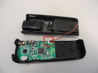
    • Use a Phillips #0 head screwdriver to remove two screws; one on either side of the circuit board.

  6. Interlink VP4550 Circuit Board Replacement: 手順 6、 1の画像 1
    • Slide the circuit board down from the tab located underneath the top of the back half

    • The laser is attached to the circuit board and will slide out of its own housing as you slide out the circuit board.

    • Use tweezers to gently remove it if it doesn't come out.

終わりに

To reassemble your device, follow these instructions in reverse order.

作成者

11人の作成者と共同で作成されました。

custer78

メンバー登録日: 02/11/14

24 ポイント

1ガイドが承認済み

チーム

Ohio State, Team 1-1, Buehl Spring 2014 Ohio State, Team 1-1, Buehl Spring 2014人のメンバー

OSU-BUEHL-S14S1G1

4 メンバー

3のガイドは作成済み

0 件のコメント

コメントを追加

統計データ:

過去 24時間: 0

過去 7 日: 0

過去 30 日: 0

今までの合計 248