メインコンテンツにスキップ

このバージョンは誤った内容を含んでいる可能性があります。最新の承認済みスナップショットに切り替えてください。

必要な工具と部品

  1. , アクセスドア: 手順 1、 2の画像 1 , アクセスドア: 手順 1、 2の画像 2
    • iMacの下部にあるアクセスドアを確認し、3本のネジを緩めます。

    • 3本のネジはアクセスドアから脱落防止加工されています。

    • アクセスドアを取り外します。

    • アクセスドアを再度取り付ける場合、それぞれのネジは最初からきつく締めないようにします。アクセスドアが正しくiMac本体にはまるように位置を調整しながら3本のネジを締めるようにしましょう。

  2. , RAM: 手順 2、 1の画像 1
    • 指やスパッジャーの先端を使って、RAMスロットから黒のプラスチック製RAMトレイプルタブをスライドして、取り出します。

  3. : 手順 3、 2の画像 1 : 手順 3、 2の画像 2
    • iMacから黒のプラスチック製タブを引き抜き、ソケットからRAMチップを取り出します。

    • RAMモジュールは、しっかりと固定されているので、取り外すには、かなりの力が必要です。

    • 指を使って、ソケットからRAMチップをスライドして、取り出します。

    • 必要に応じて、他のRAMモジュールに対してもこの手順を繰り返します。

  4. , ガラスパネル: 手順 4、 3の画像 1 , ガラスパネル: 手順 4、 3の画像 2 , ガラスパネル: 手順 4、 3の画像 3
    この手順で使用する道具:
    Heavy-Duty Suction Cups (Pair)
    $14.95
    購入する
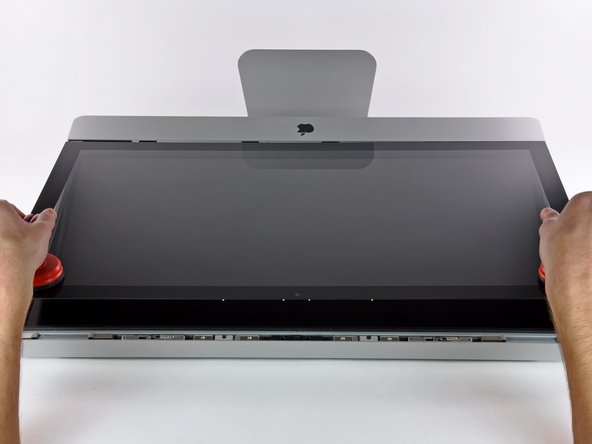
    • ガラスパネルの上部コーナー付近の2箇所に、重量用の吸盤カップを取り付けます。

    • 吸盤カップを装着するには、まず可動ハンドルがガラスパネル表面と平行になるように吸盤カップを載せます。(2番目の画像を参照してください。)

    • 吸盤カップをガラスに軽く当てながら、可動ハンドルをもう一方のハンドルと平行になるまで持ち上げます。(3番目の画像を参照してください。)

    • 吸盤が上手く固着しない場合は、ガラスパネルと吸盤カップの両方を柔らかくリントフリー(メガネ拭きなど)の布を湿らせて軽く拭きます。( 一番効果的な方法は、蒸留水、もしくは蒸留水と白酢を同じ割合で調合したものを布に含ませます。)

    • 吸盤カップを使ってディスプレイガラスを運ばないでください。吸盤カップのいずれか上手く固着されていないと、スクリーンが落下して壊れてしまう可能性があります。

    • 購入時のオリジナルiMac用梱包ボックスは、ガラスパネルを保管するのに最適な場所です。 それ以外は、安定した水平上の表面、机の上にタオルを敷いた上に載せておくと安全です。

  5. : 手順 5、 3の画像 1 : 手順 5、 3の画像 2 : 手順 5、 3の画像 3
    • ガラスパネル上部端の裏側に沿って付けられたスチール製の取り付けピンが外れるように、LCDパネル表面に対してガラスパネルを垂直に、ゆっくりと持ち上げます。

    • ガラスパネルをiMac下端端から引き離し、慎重に脇に置きます。

    • 吸盤カップを使用してガラスパネルを運ばないでください。どちらかのグリップを失うと、パネルが落下して破損する可能性があります。

    • ガラスパネルを安全に下ろした後、時間の経過とともに吸引力が弱まり、ガラスが割れてしまう危険性があるため、吸盤カップを必ず外してください。

    • 再装着の際は、ガラスパネル内側とLCDの表面を慎重に拭いてください。デバイス本体の電源を入れると、ほこりや指紋が内部に閉じ込められています。

  6. , 液晶パネル: 手順 6、 1の画像 1
    • 液晶パネルとアウターケースを固定しているT10 トルクスネジ × 8本を外します

    • 油脂が付着すると取れにくいし場合がありますので、液晶面に指が触れないようご注意ください。

    • 必要に応じて、液晶上部中央付近のEMIガスケットを剥がします。

  7. , ディスプレイ: 手順 7、 3の画像 1 , ディスプレイ: 手順 7、 3の画像 2 , ディスプレイ: 手順 7、 3の画像 3
    • iMacを慎重に平らな面に起きます。

    • タイトに装着されているため、液晶パネルを持ち上げるには、画像にあるように紙クリップを使って細いフック状の工具を作成してください。

    • もしくは、iFixit特製デュアルハードドライブキットには、持ち上げるのに最適なアングル付きピンセットが含まれています。

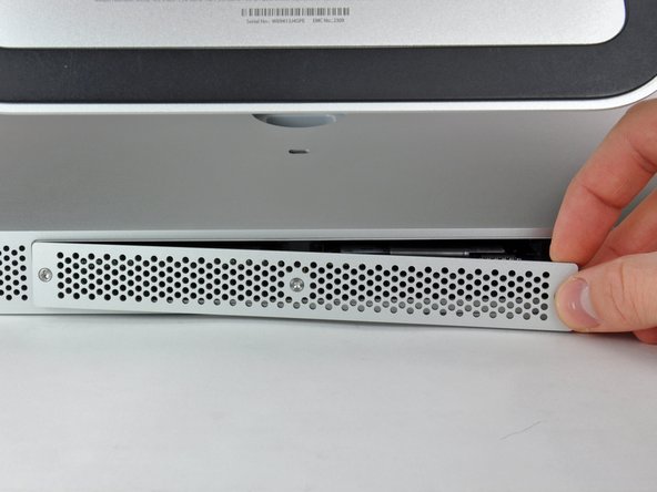
    • 細いフック状の工具で左右どちらか一方の上端角から液晶パネルを引き上げ、フレームから外します。

    • 液晶パネルの一方を持ち上げたら、ケースの外にかけ、もう片方を同様に工具を使って外ケースから持ち上げます。

    • ケーブルにアクセスできるように、液晶パネルを、ゆっくりかつ十分に開きます。

    • 液晶パネル裏面に着いている短いリボンケーブルが2つのパーツに接続されているので、パネルの上部端をあまり高く持ち上げないでください。

  8. : 手順 8、 1の画像 1
    • 画面の左上の隅の裏側にある垂直同期ケーブルを外しましょう。スパッジャーの先端をうまく利用してコネクタの側面の突起をソケットから慎重にスライドして押し出します。

  9. : 手順 9、 1の画像 1
    • この作業では、素手を電源ユニットの背面に差し入れます。電源ユニットの背面のボードがむき出しになっていますが、大容量コンデンサに帯電している高電圧の電流が流れますので、絶対に触れないでください。

    • 手でコネクタのつまみを押し下げながらディスプレイ下部に向かってずらし、液晶パネルのLEDケーブルを外します。

  10. : 手順 10、 2の画像 1 : 手順 10、 2の画像 2
    • コネクタに付いている黒いつまみを画面上部に引っ張り上げることで、液晶パネルケーブルのZIFコネクタを外せます。

    • コネクタとソケットにダメージを与える可能性があるので、強く引っ張らないでください。

    • ディスプレイデーターケーブルを外すには、コネクタの黒いタブをデバイス上部に向けて、続けて引っ張ります。

  11. : 手順 11、 1の画像 1
    • スパッジャーの先端を使用して、ディスプレイデータケーブルの横にあるディスプレイ電源ケーブルを取り外します。

  12. : 手順 12、 1の画像 1
    • 液晶パネルを上部端に向けて注意深く引き上げ、液晶パネルをiMac本体から持ち上げて取り出します。

  13. : 手順 13、 1の画像 1
    • ディスプレイの面を柔らかくて平らな表面の場所に置きます

    • ディスプレーパネルを交換する際は、ディスプレイに付属している全ての部品を新しいディスプレイへ移植する必要があります。新旧のディスプレーを比較して、全てのケーブル、センサー、クッションが移植されていることを確認してください。

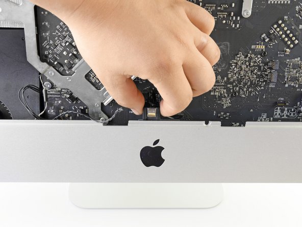
    • もしそこに、粘着テープ付きハーネスかケーブルがあった場合、直接ケーブルを引っ張らず、必ずテープを先にはがし取ってください。

    • ケーブルがシャーシに接着剤で固定されている場合、iOpenerかドライヤーを用いて熱し、接着剤を軟化させてください。その後にopening pickをケーブルの下に挿入し、ケーブルを緩めてください。デリケートなコネクターがあるため強引に引っ張ることは避けてください。

    • フォームクッションの下にopening pickをスライドして、少しずつディスプレーから分離し、優しく引っ張ります。取り外したこのクッションを再度新しいディスプレーへ接着するために、新しい両面テープを用意する必要があります。

  14. , 光学ドライブ: 手順 14、 1の画像 1
    • スパッジャーの平面側先端を使って、光学ドライブから光学ドライブデータケーブルを引き抜きます。

  15. : 手順 15、 1の画像 1
    • スパッジャーの先端を使って、ソケットから高額ドライブサーマルセンサーのコネクタを引き抜きます。

  16. : 手順 16、 1の画像 1
    • 光学ドライブをiMacケースに固定しているT10トルクスネジを4本外します。

    • 左下のネジは他のネジと比べてわずかにネジ頭が広いです。

  17. : 手順 17、 2の画像 1 : 手順 17、 2の画像 2
    • 光学ドライブの左端をわずかに持ち上げて、横に引いてセンタリングピンを外します。

    • 光学ドライブを取り外す際に、サーマルセンサーケーブルを切断しないようにご注意ください。

  18. この手順は未翻訳です。 翻訳を手伝う。

    : 手順 18、 1の画像 1
    • Use the flat end of a spudger to pull the optical drive fan connector out of its socket.

  19. この手順は未翻訳です。 翻訳を手伝う。

    : 手順 19、 1の画像 1
    • Use the tip of a spudger to pull the SD board data cable connector out of its socket.

  20. この手順は未翻訳です。 翻訳を手伝う。

    : 手順 20、 1の画像 1
    • Use the flat end of a spudger to push the I/O cable connector out of its socket.

    • Alternate pushing on the tabs on the side of the connector to "walk" the connector out of its socket.

  21. この手順は未翻訳です。 翻訳を手伝う。

    : 手順 21、 1の画像 1
    • Use the flat end of the spudger to pull the microphone cable connector free of its socket.

  22. この手順は未翻訳です。 翻訳を手伝う。

    : 手順 22、 2の画像 1 : 手順 22、 2の画像 2
    • Release the right and left speaker connectors from their sockets using the flat end of a spudger.

  23. この手順は未翻訳です。 翻訳を手伝う。

    : 手順 23、 2の画像 1 : 手順 23、 2の画像 2
    • Locate the AirPort card at the top center of the logic board and just below the hard drive.

    • Use the flat end of a spudger to gently pry each of the antenna cables off their sockets.

    • Do not disconnect the antennas by pulling on the cables as this may damage the cables, connectors, or sockets.

    • The antennas have markings to help you identify their order. The antenna with no marks goes to "CH0", the antenna with one mark goes to "CH1", and the antenna with two marks goes to "CH2".

  24. この手順は未翻訳です。 翻訳を手伝う。

    : 手順 24、 1の画像 1
    • Use the flat edge of a spudger to push the camera/Bluetooth/ambient light sensor connector out of its socket.

  25. この手順は未翻訳です。 翻訳を手伝う。

    : 手順 25、 1の画像 1
    • Release the hard drive fan connector from its socket by pushing on its tabs using the flat end of a spudger.

  26. この手順は未翻訳です。 翻訳を手伝う。

    : 手順 26、 1の画像 1
    • Push the thermal sensor connector out of its socket with the flat end of a spudger.

  27. この手順は未翻訳です。 翻訳を手伝う。

    : 手順 27、 1の画像 1
    • Use the flat edge of a spudger to release the CPU fan cable

  28. この手順は未翻訳です。 翻訳を手伝う。

    : 手順 28、 1の画像 1
    • Use the flat end of the spudger to push the ambient temperature sensor connector out of its socket.

  29. この手順は未翻訳です。 翻訳を手伝う。

    : 手順 29、 1の画像 1
    • Use the flat edge of a spudger to pull the power button connector free of its socket.

  30. この手順は未翻訳です。 翻訳を手伝う。

    : 手順 30、 2の画像 1 : 手順 30、 2の画像 2
    • Locate the IR sensor located behind the black Apple logo.

    • If necessary, peel back the tape covering the IR sensor.

    • Detach the IR sensor by pulling it straight up and out from the case.

    • Do not attempt to completely remove the IR sensor from the iMac as it is still attached to the logic board.

  31. この手順は未翻訳です。 翻訳を手伝う。

    : 手順 31、 1の画像 1
    • Remove the eight T10 Torx screws securing the logic board and heat sink assembly to the iMac case.

  32. この手順は未翻訳です。 翻訳を手伝う。

    : 手順 32、 2の画像 1 : 手順 32、 2の画像 2
    • Simultaneously lift and rotate the logic board and heat sink assembly away from the iMac case until you can easily access the back side of the logic board.

  33. この手順は未翻訳です。 翻訳を手伝う。

    : 手順 33、 2の画像 1 : 手順 33、 2の画像 2
    • Locate the secondary SATA socket, next to the primary SATA socket.

    • Plug in the included SATA data/power cable.

    • The hard drive cable side with only one connector goes into the logic board connector.

  34. この手順は未翻訳です。 翻訳を手伝う。

    : 手順 34、 2の画像 1 : 手順 34、 2の画像 2
    • Route the new SATA cable through the indentation that the primary SATA cable goes through and into the optical drive bay.

    • Not all of the 27” iMacs (2011) have the channel in the optical drive wall to route SSD cabling. If you have one of these iMacs, you can simply route the cables under the optical drive.

    • Set the logic board back into place, being careful not to catch, cover, or pinch any cables.

    • Be sure that the SATA cable has as much slack as possible and that it is not tangled with any other cables.

    • Make sure the cables are not stacked on top of each other; they have to lay as flat as possible

  35. この手順は未翻訳です。 翻訳を手伝う。

    : 手順 35、 3の画像 1 : 手順 35、 3の画像 2 : 手順 35、 3の画像 3
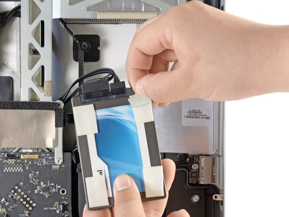
    • To secure your new drive in your iMac, you will need to place high strength double-sided tape at the four corners on the side of the drive with the SATA connectors.

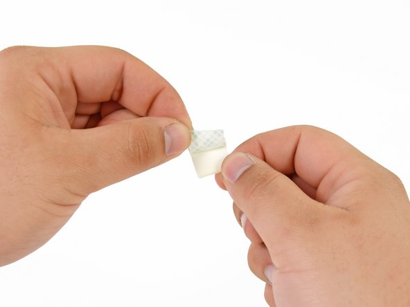
    • Peel the backing off one side of the double sided tape.

    • Press the exposed adhesive side of the double sided tape to the corner of the SSD.

    • Be sure not to cover the SATA connectors with the double sided tape.

    • Repeat the above process for the remaining 3 corners.

  36. この手順は未翻訳です。 翻訳を手伝う。

    : 手順 36、 3の画像 1 : 手順 36、 3の画像 2 : 手順 36、 3の画像 3
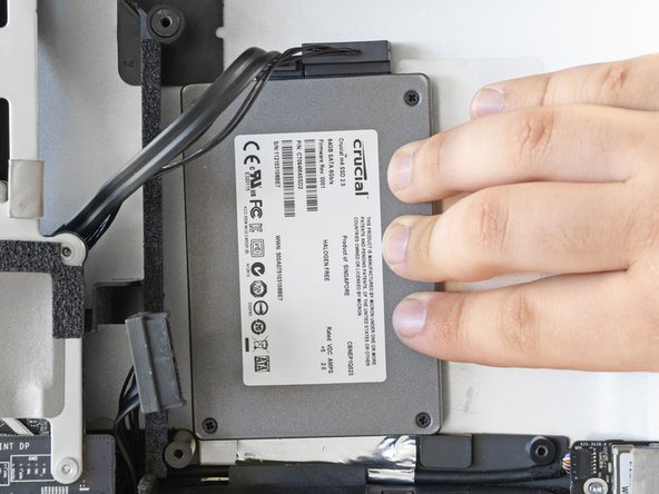
    • Connect both the SATA data and SATA power connectors to their respective sockets on the SSD.

    • Peel the backing off of the double sided tape.

    • Carefully set the SSD into the iMac optical bay as close to the lower left corner as possible.

    • Do not repeatedly stick and un-stick the tape, as the adhesive will become weaker.

    • Once you are happy with the SSD's placement, firmly press down along its edges to ensure full adhesion.

    • When re-installing the optical drive, the SATA cable will be sandwiched between the foam padding and the optical drive.

ゴール

355 の人々がこのガイドを完成させました。

作成者

19人の作成者と共同で作成されました。

Phillip Takahashi

メンバー登録日: 08/22/11

86,704 ポイント

87のガイドは作成済み

71 件のコメント

Don´t forget to take out the RAM first. Otherwise it is very difficult to replace the logic board back in it´s place.

B Riefel - 返信

Excellent guide. Thank you!

I got through everything, turned on the iMac, got the start up gong, and ... nothing. Screen stayed black and the fans started blowing like crazy, indicating failure of Apple Hardware Test. All my attempts to remedy (zap PRAM, reset SMC) failed. Uh oh.

Opened the machine back up, took out the LCD, and re-seated all four connections from display panel to logic board. Crossed my fingers and put it back together. This time, the displayed turned on, the Apple logo appeared, system booted up, and the new SSD appeared on the desktop. Yay!

The connectors from the LCD are delicate. It's tricky to seat them properly without damaging them, but don't close it up without a positive click on each one.

The upgrade has been fantastic so far. SanDisk 120GB SSD. Dramatic speed improvement. Well worth all the surgery on the machine.

claytonhibbert - 返信

in step 22 you can see the wifi cables are not connected anymore. but there is no step that shows you should disconnect them

R Sonnema - 返信

+1 Unfortunately mine has been broken (CH1 cable is out from the UFL connector). Unfortunately I do not now how to repair it.

It would be important to add this step in order to protect others falling into the same issue.

PeterZ -

i followed this guide to the T. used a 240gig Corsair GS and after it gets far along the boot process the fans blow at max speed! i took the monitor off again to make sure i had all the connections in the right place. there was one i was missing... the ambient temp lol. but i plugged it back in and still fans blow full blast :( gonna keep messing with it to see if i can figure it out :)

paulhizo - 返信

コメントを追加

統計データ:

過去 24時間: 19

過去 7 日: 121

過去 30 日: 508

今までの合計 440,650