メインコンテンツにスキップ

このバージョンは誤った内容を含んでいる可能性があります。最新の承認済みスナップショットに切り替えてください。

必要な工具と部品

  1. , アクセスドア: 手順 1、 2の画像 1 , アクセスドア: 手順 1、 2の画像 2
    • iMacのACコードを周辺機器と一緒に抜きます。

    • 画像のように、iMacを柔らかく清潔な場所に裏返して置きます。

    • iMacのフロントに搭載されているガラスパネルに傷がつかないように、作業台上には汚れや異物などがないか確認してください。iMacと作業台の間にタオルを敷くことをお勧めします。

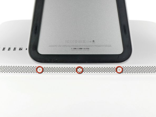
    • iMacの下側端とアクセスドアを固定している3本のプラスネジを緩めます。

    • 3本のネジはすべてアクセスドアに固定されています。

    • アクセスドアを取り出します。

  2. , RAM: 手順 2、 3の画像 1 , RAM: 手順 2、 3の画像 2 , RAM: 手順 2、 3の画像 3
    • 黒いプラスチックのRAM用プルタブをRAMスロットからゆっくりとスライドします。

    • 黒いプラスチック製のタブをiMac下端の底から引き離して、RAMベイ側に搭載されているモジュールを取り出します。

    • 作業には若干力が必要です。

  3. : 手順 3、 1の画像 1
    • RAMベイのスロットから古いRAMモジュールをスライドして取り出します。

  4. : 手順 4、 3の画像 1 : 手順 4、 3の画像 2 : 手順 4、 3の画像 3
    • 前の手順を繰り返して、RAMベイの反対側からRAMモジュールを取り出します。

  5. : 手順 5、 3の画像 1 : 手順 5、 3の画像 2 : 手順 5、 3の画像 3
    • 新しいRAMモジュールを装着する際は、正しい方向に取り付けることが重要です。

    • 各RAMモジュールに切り込まれた小さなノッチ(1番目の画像で確認できます)がRAMスロットの突起と合わさります。(2番目の画像を参照ください)

    • お持ちのiMacに4つのRAMスロットがあります。各モジュールを差し込む際は、スロットに対して水平にスライドします。隣り合う二つのスロットの間でモジュールが詰まるのを防ぐことができます。

    • 正しい装着方向を確認できたら、RAMモジュールをゆっくりとiMacにスライドします。親指を使って、各ソケット上にしっかりと固定してください。

  6. , ガラスパネル: 手順 6、 2の画像 1 , ガラスパネル: 手順 6、 2の画像 2
    この手順で使用する道具:
    Heavy-Duty Suction Cups (Pair)
    $14.95
    購入する
    • 作業を始める前に、iMacの電源を切り、画像のように本体を倒して、柔らかい表面上に載せてください。

    • ガラスパネルの上部コーナーの2箇所に吸盤カップを取り付けます。

    • iFixitが販売している吸盤カップを取り付けるには、まず吸盤カップの持ち手ハンドルをガラスパネルの表面に対して水平になるように上げてください。ガラスに吸盤カップを軽く装着して、もう一方のハンドルも平行になるように上げてください。

    • 吸盤カップがうまく装着しない場合は、ガラスパネルと吸盤カップを中性洗剤などで綺麗に拭き取ってください。

  7. : 手順 7、 2の画像 1 : 手順 7、 2の画像 2
    • ゆっくりとガラスパネルをLCD表面に垂直になるように持ち上げて、スチール製のマウントピン

    • ガラスパネルをiMacの底側端から引き抜き、丁寧に脇に置いてください。

    • 再組み立ての際には、ガラスパネルの内側やLCD表面を綺麗に拭いてください。デバイスの電源を入れると、ほこりや指紋が内部に閉じ込められ、視界が遮られてしまうことがあります。

  8. , ディスプレイ: 手順 8、 3の画像 1 , ディスプレイ: 手順 8、 3の画像 2 , ディスプレイ: 手順 8、 3の画像 3
    • アウターケースにディスプレイを固定している8 mm T10トルクスネジを8本外します。

    • 最後2枚の画像はディスプレイ両サイドの詳細な様子です。

  9. : 手順 9、 1の画像 1
    • アウターケースからディスプレイの上部端をわずかに持ち上げます。

    • あまり高く持ち上げすぎないでください。ディスプレイとロジックボードには数本のケーブルが接続されたままです。ケーブルが付いたままディスプレイアセンブリをひねったり、引っ張るとiMac本体にダメージを与えてしまいます。

  10. : 手順 10、 2の画像 1 : 手順 10、 2の画像 2
    • iMacの左上隅付近にあるLEDドライバボードのソケットから垂直同期ケーブルコネクタを引き抜きます。

  11. : 手順 11、 2の画像 1 : 手順 11、 2の画像 2
    • LEDドライバボードから、LEDバックライトの電源ケーブルの接続を外すため、ディスプレイをアウターケースから回転させて取り出します。

    • コネクタをソケットから引き離しながら(iMacの下端に向かって)ロック機構を押し下げ、LEDバックライト電源ケーブルの接続を外します。

  12. : 手順 12、 3の画像 1 : 手順 12、 3の画像 2 : 手順 12、 3の画像 3
    • ディスプレイデータケーブルのロックに固定されたプラスチックのプルタブを掴み、上向きに回転させます。

    • ディスプレイデータケーブルを、ロジックボード上のソケットからまっすぐ引き抜きます。

    • ディスプレイデータケーブルを上向きに引き抜かないでください。このソケットは壊れやすいためです。ケーブルをロジックボードの表面と並行に引っ張ります。

  13. : 手順 13、 2の画像 1 : 手順 13、 2の画像 2
    • ロジックボード上のソケットからLCD温度センサーのケーブルコネクタの接続を外します。

  14. : 手順 14、 1の画像 1
    • 慎重にディスプレイをiMac上部端に向けて引き抜き、アウターケースから持ち上げます。ケーブルが巻き込まれないようご注意ください。

  15. , 光学ドライブ: 手順 15、 1の画像 1
    • ここから、デバイス本体を裏返して、ベース部分を上向きにすると作業がしやすくなります。

    • 次の4本のネジを外します。

    • 9.3 mm T10 トルクスネジ(大)ー1本

    • 9.3 mm T10トルクスサイズ(通常サイズ)ー3本

  16. : 手順 16、 2の画像 1 : 手順 16、 2の画像 2
    • ロジックボード上のソケットから光学ドライブ温度センサのコネクタをまっすぐ引き抜きます。上向きに引くのではなく、ボードに並行になるように抜いてください。

  17. : 手順 17、 2の画像 1 : 手順 17、 2の画像 2
    • 光学ドライブ内側の端を持ち上げて、ロジックボードに付いているGPUフレームのコネクタを絡まないように外してください。

    • 光学ドライブをアウターケース右側に付いている固定ピンから慎重に引き抜き、光学ドライブケーブルの接続を外すためにスペースを確保します。

    • GPUヒートシンクの後ろから光学ドライブ温度センサのコネクタを取り外すには、光学ドライブの後ろを通してください。

  18. : 手順 18、 1の画像 1
    • 光学ドライブから光学ドライブのコネクタを引き抜いて、光学ドライブケーブルの接続を外します。

    • iMacから光学ドライブを取り出します。

  19. , 光学ドライブファン: 手順 19、 1の画像 1
    • 光学ドライブのファンをアウターケースに固定している13 mm T10トルクスネジを1本外します。

  20. : 手順 20、 1の画像 1
    • アウターケースに固定されたピンから光学ドライブファンを引き抜きます。

  21. : 手順 21、 1の画像 1
    • ロジックボード上のソケットから光学ドライブのファンコネクタを引き抜きます。

    • iMacから光学ドライブを取り出します。

  22. この手順は未翻訳です。 翻訳を手伝う。

    : 手順 22、 1の画像 1
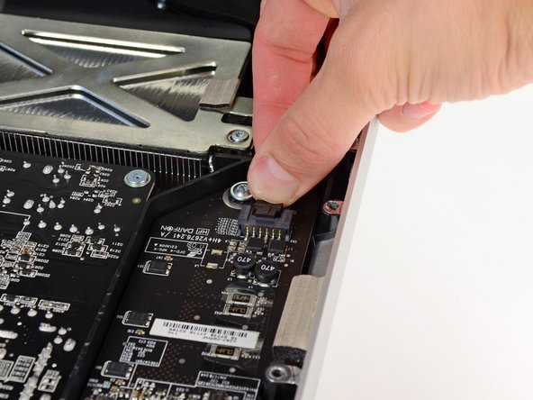
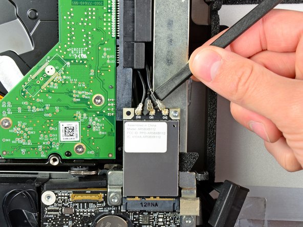
    • In the proceeding steps, you will disconnect the following cables:

    • SD Board

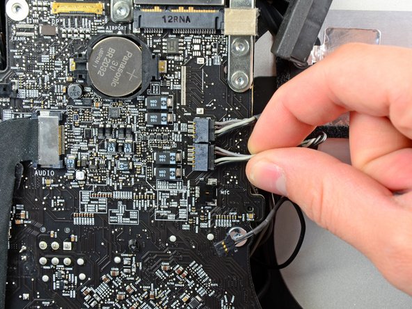
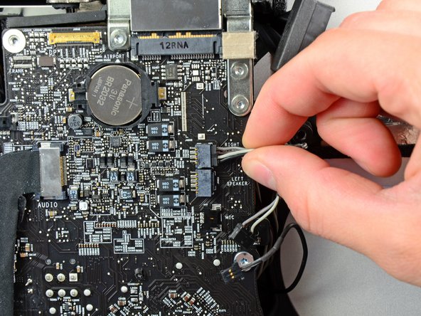
    • Left/Right Speaker and Microphone

    • Audio Port

    • Wi-Fi Antenna

    • Right Temperature Sensor, Bluetooth/Ambient Light Sensor/Camera/Left Temperature, and Hard Drive Fan

    • CPU Fan/Ambient Temperature and Power Button

    • IR Sensor

  23. この手順は未翻訳です。 翻訳を手伝う。

    : 手順 23、 1の画像 1
    • Pull the SD board cable out of its socket on the logic board.

  24. この手順は未翻訳です。 翻訳を手伝う。

    : 手順 24、 3の画像 1 : 手順 24、 3の画像 2 : 手順 24、 3の画像 3
    • Disconnect the microphone, left speaker, and right speaker cables by pulling their connectors toward the right side of the iMac.

  25. この手順は未翻訳です。 翻訳を手伝う。

    : 手順 25、 2の画像 1 : 手順 25、 2の画像 2
    • Use the flat end of a spudger to pry all three AirPort antenna connectors up from their sockets on the AirPort board.

    • During reinstallation, connect the cable with no stripes to the socket marked CH0, the cable with one stripe to CH1, and the cable with two stripes to CH2.

  26. この手順は未翻訳です。 翻訳を手伝う。

    : 手順 26、 1の画像 1
    • Pull the hard drive fan connector toward the top edge of the iMac to disconnect it from its socket on the logic board.

  27. この手順は未翻訳です。 翻訳を手伝う。

    : 手順 27、 1の画像 1
    • Use your thumbnails on both sides of the Bluetooth/ambient light sensor/camera/left temperature connector to push it toward the top edge of the iMac and out of its socket on the logic board.

  28. この手順は未翻訳です。 翻訳を手伝う。

    : 手順 28、 1の画像 1
    • Use your thumbnails to push the right temperature sensor connector toward the top edge of the iMac and out of its socket.

  29. この手順は未翻訳です。 翻訳を手伝う。

    : 手順 29、 1の画像 1
    • Pull the CPU fan/ambient temperature sensor connector toward the bottom left edge of the iMac and out of its socket on the logic board.

  30. この手順は未翻訳です。 翻訳を手伝う。

    : 手順 30、 1の画像 1
    • Pull the power button connector toward the bottom left corner of the iMac to disconnect it from its socket on the logic board.

  31. この手順は未翻訳です。 翻訳を手伝う。

    : 手順 31、 2の画像 1 : 手順 31、 2の画像 2
    • Use your thumbs to push the IR sensor connector toward the top edge of the iMac and out of its socket on the logic board.

    • Pull the IR sensor board up from behind the front face of the outer case.

    • Remove the IR sensor and set it aside.

  32. この手順は未翻訳です。 翻訳を手伝う。

    : 手順 32、 2の画像 1 : 手順 32、 2の画像 2
    • Pull the audio port cable connector toward the left side of the iMac to disconnect it from the logic board.

    • Do not pull the cable toward yourself (away from the front face of the logic board) as you disconnect it.

    • Peel the audio port cable off the front face of the logic board and let it hang down as shown in the second picture.

  33. この手順は未翻訳です。 翻訳を手伝う。

    : 手順 33、 1の画像 1
    • Remove the following seven screws:

    • Two 7 mm T10 torx screws

    • One 30 mm T10 Torx screw

    • Two 25 mm T10 Torx screws

    • Two 21 mm T10 Torx screws

  34. この手順は未翻訳です。 翻訳を手伝う。

    : 手順 34、 2の画像 1 : 手順 34、 2の画像 2
    • Remove the following four screws from the power supply:

    • One 9.3 mm T10 coarse-threaded screw

    • One 25 mm T10 coarse-threaded screw

    • Two 22 mm fine-threaded screws

    • Pull the upper right and lower left corners of the power supply away from the rear case to dislodge the mounting posts attached to the power supply's corners.

  35. この手順は未翻訳です。 翻訳を手伝う。

    : 手順 35、 2の画像 1 : 手順 35、 2の画像 2
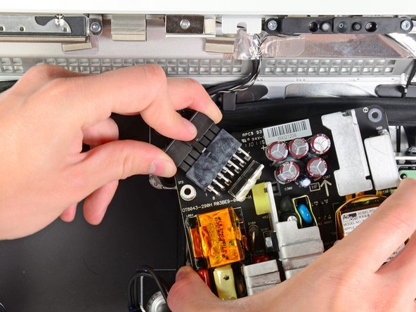
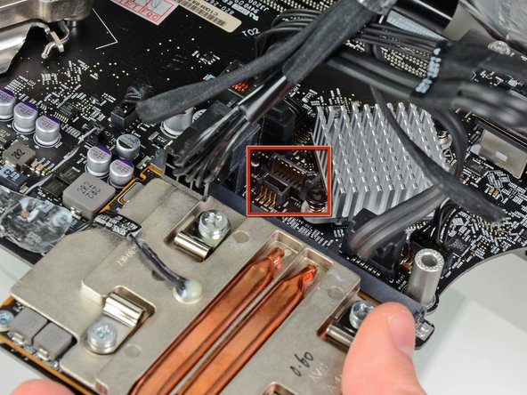
    • Carefully lift the power supply out of the outer case and rotate it to expose the cable lock as shown, minding the DC-out and AC-in cables still attaching it to the iMac.

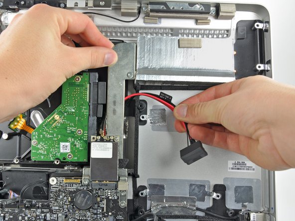
    • Disconnect the DC-out cable by depressing the locking mechanism on the connector while you pull the connector away from its socket on the power supply.

    • Once the locking mechanism has cleared the socket, pull the DC-in connector away from the power supply.

  36. この手順は未翻訳です。 翻訳を手伝う。

    : 手順 36、 1の画像 1
    • Disconnect the AC-In cable by depressing the locking mechanism while pulling the connector away from its socket.

    • Remove the power supply from the outer case.

  37. この手順は未翻訳です。 翻訳を手伝う。

    : 手順 37、 1の画像 1
    • Remove the plastic wall that is installed directly to the right of the LED driver board.

  38. この手順は未翻訳です。 翻訳を手伝う。

    : 手順 38、 2の画像 1 : 手順 38、 2の画像 2
    • Slightly pull the logic board away from the back of the outer case, then lift it upward to clear the lower front face of the outer case.

  39. この手順は未翻訳です。 翻訳を手伝う。

    : 手順 39、 1の画像 1
    • In the following steps, you will hold the logic board slightly away from the outer case as you connect the new hard drive cables included with the dual hard drive kit.

    • As you connect the cables, do not put excessive strain on any of the other cables connecting the logic board to the outer case.

  40. この手順は未翻訳です。 翻訳を手伝う。

    : 手順 40、 1の画像 1
    • First, locate the small connector on the SSD power cable.

  41. この手順は未翻訳です。 翻訳を手伝う。

    : 手順 41、 1の画像 1
    • Connect the small plug on the SATA power cable to the socket labeled SSD Power on the logic board.

    • The socket is located just below the GPU heat sink.

  42. この手順は未翻訳です。 翻訳を手伝う。

    : 手順 42、 1の画像 1
    • Next, locate the 90º connector on one end of the SATA data cable.

    • The color of your SATA data cable may be different than the cable shown here.

  43. この手順は未翻訳です。 翻訳を手伝う。

    : 手順 43、 1の画像 1
    • Connect the 90º end of the SATA data cable to its socket on the logic board next to the SATA power connector.

  44. この手順は未翻訳です。 翻訳を手伝う。

    : 手順 44、 1の画像 1
    • With both SATA cables connected, they should look like the logic board shown in the photo.

  45. この手順は未翻訳です。 翻訳を手伝う。

    : 手順 45、 2の画像 1 : 手順 45、 2の画像 2
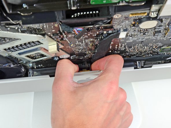
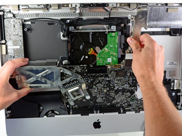
    • Next, while holding the new hard drive cables against the GPU heat sink, lower the bottom edge of the logic board back down into the outer case.

    • When re-seating the logic board, it is helpful to tape the many connectors that attach to it out of the way to avoid them getting trapped beneath the board.

    • Before pushing the logic board against the back of the outer case, first route the hard drive cables in the channel near the bundle of power cables.

    • As you place the logic board into its recess, route the hard drive cables through the small channel cut into the plastic pressure wall near the fins of the GPU heat sink.

  46. この手順は未翻訳です。 翻訳を手伝う。

    : 手順 46、 1の画像 1
    • In the next few steps, you'll install your new drive into the case of your EMC 2428 iMac.

    • The drive will sit behind the optical drive in the space highlighted in red.

  47. この手順は未翻訳です。 翻訳を手伝う。

    : 手順 47、 3の画像 1 : 手順 47、 3の画像 2 : 手順 47、 3の画像 3
    • To secure your new drive in your iMac, you will need to place high strength double-sided tape at the four corners on the side of the drive with the SATA connectors.

    • Peel the backing off one side of the double-sided tape and place the pieces at the four corners of the hard drive.

  48. この手順は未翻訳です。 翻訳を手伝う。

    : 手順 48、 2の画像 1 : 手順 48、 2の画像 2
    • Connect both the SATA data and SATA power connectors to your new hard drive.

    • The SATA connectors will be nearest the top of the iMac when the hard drive is installed.

  49. この手順は未翻訳です。 翻訳を手伝う。

    : 手順 49、 2の画像 1 : 手順 49、 2の画像 2
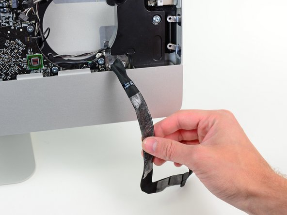
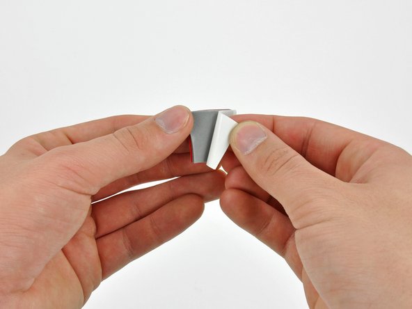
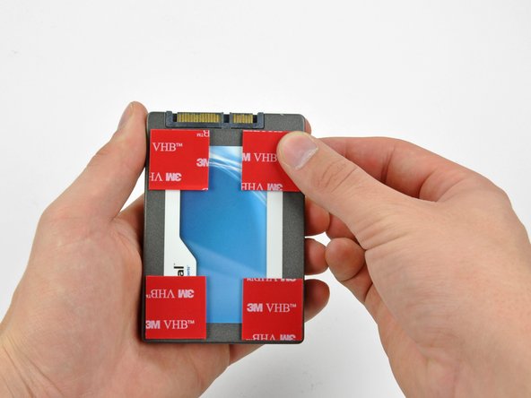
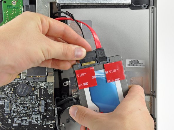
    • Remove the backing from the double-sided tape and place the hard drive inside the iMac.

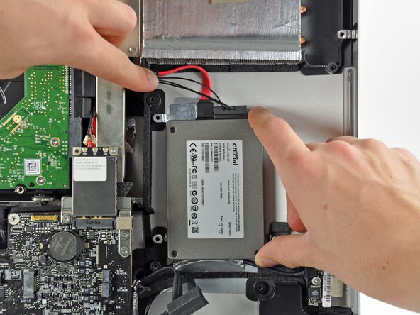
    • Carefully set the drive into the iMac optical bay as close to the lower left corner as possible.

    • Do not to repeatedly stick and un-stick the tape, as the adhesive will become weaker.

    • Once you are happy with the hard drive's placement, firmly press down along its edges to ensure full adhesion.

ゴール

272 の人々がこのガイドを完成させました。

作成者

12人の作成者と共同で作成されました。

Andrew Bookholt

586,296 ポイント

619のガイドは作成済み

72 件のコメント

It should be noted to anyone doing this that RAM should be removed first. When you get towards the end things go bad if your RAM is still in there and you start moving the mainboard around.

azkaban1 - 返信

You are correct. I followed the ifixit guide on youtube and it was not mentioned to remove the RAMs. But in fact the RAMs should be removed in order to pull the logic board.

Mohamed Kamal -

Seconded ... remove ram first! Spent more time reinstalling main board than anything else.

Added bigger HDD as well as SSD. Buy HDD Fan Control to fix fan speed.

A curse on Jobs & Apple for making it this tedious to add SSD & HDD.

Cudos to ifixit!

tonybaczynski - 返信

Did it, my imac is extreamly speedy now with the ssd compared with the origional hdd.

Tool me about two hours to do, had to have my brother help me when i was removing the logic board and screen.

Found that the logic board was extreamly hard to remove.

Good tip is to selotape the cables before removing / inserting the logic board as i traped my microphone connector underneath. Luckely i could reach it with a pair of tweesers.

Over all glad i did it.

garethvincenthall - 返信

Can anybody explain why the PSU module needs to be removed (steps 34-37)? I saw a similar guide elsewhere and it skipped this completely. Is this not required? If so, that might explain why this guide says that to re-assemble do the reverse from step 33 and not 38 as expected!

markbart - 返信

コメントを追加

統計データ:

過去 24時間: 5

過去 7 日: 106

過去 30 日: 463

今までの合計 317,771