メインコンテンツにスキップ

このバージョンは誤った内容を含んでいる可能性があります。最新の承認済みスナップショットに切り替えてください。

必要な工具と部品

  1. , 下部ケース: 手順 1、 1の画像 1
    • 下部ケースを上部ケースに固定している次の10本のネジを外します:

    • 13.5mmプラスネジ 3本

    • 3mmプラスネジ 7本

  2. : 手順 2、 2の画像 1 : 手順 2、 2の画像 2
    • 下部ケースとベントの間に指を差し込み、下部ケースと上部ケースを固定している二つのクリップを外しながら持ち上げます。

    • 再組み立ての際には、下部ケースの位置を揃えてください。それからクリップが装着するまでしっかりと押し込みます。

    • 下部ケースを取り外します。

  3. , バッテリー: 手順 3、 3の画像 1 , バッテリー: 手順 3、 3の画像 2 , バッテリー: 手順 3、 3の画像 3
    • ロジックボードの近くで作業するときは、最初にバッテリーを外してください。

    • バッテリーコネクタに取り付けられているプラスチックのタブを掴み、デバイス前端に向けて引っ張ります。 Late 2011モデルでは、バッテリコネクタにタブが付いておらず、差し込み口をマザーボードの内部に取り付けるだけです。そのため、外すにはプラグをまっすぐ持ち上げます。

    • プラスチックのタブが付いてない場合、スパッジャーを使用して、ソケットからコネクタを引き上げます。

    • ロジックボード表面に、タブを並行に引きます。

  4. この手順は未翻訳です。 翻訳を手伝う。

    : 手順 4、 1の画像 1
    • Before disconnecting the camera cable, a small plastic retainer stuck to the logic board must first be moved out of the way.

    • Use the tip of a spudger to push the small plastic cable retainer away from the camera cable socket for enough clearance to remove the camera cable.

  5. この手順は未翻訳です。 翻訳を手伝う。

    : 手順 5、 1の画像 1
    • Pull the camera cable toward the optical drive opening to disconnect it from the logic board.

    • The camera cable socket is very fragile. Do not apply any upward force to this socket, as it may break off the logic board. Pull the camera cable parallel to the face of the logic board.

    • For Late 2011 models, the camera connector plugs straight down into the motherboard—to remove this connector, gently lift it straight up.

  6. この手順は未翻訳です。 翻訳を手伝う。

    : 手順 6、 1の画像 1
    • Carefully pull the Bluetooth cable toward the fans to disconnect it from the Bluetooth board.

    • Pull the cable parallel to the face of the optical drive.

  7. この手順は未翻訳です。 翻訳を手伝う。

    : 手順 7、 1の画像 1
    • Use the flat end of a spudger to peel the thin plastic cover off the top and sides of the Bluetooth board housing.

  8. この手順は未翻訳です。 翻訳を手伝う。

    : 手順 8、 1の画像 1
    • Use the flat end of a spudger to pry the Bluetooth antenna connector up and off its socket on the Bluetooth board.

  9. この手順は未翻訳です。 翻訳を手伝う。

    : 手順 9、 2の画像 1 : 手順 9、 2の画像 2
    • If present, remove the small piece of EMI foam near the Bluetooth board.

    • De-route the camera cable from the slot molded into the Bluetooth board housing.

  10. この手順は未翻訳です。 翻訳を手伝う。

    : 手順 10、 1の画像 1
    • Use the flat end of a spudger to pry the optical drive connector up and out of its socket on the logic board.

  11. この手順は未翻訳です。 翻訳を手伝う。

    : 手順 11、 1の画像 1
    • Remove the three 3.5 mm Phillips screws securing the optical drive to the upper case.

    • To remove the screw closest to the battery, it may be helpful to use a T6 Torx screwdriver to first remove the upper case bracket directly above it.

  12. この手順は未翻訳です。 翻訳を手伝う。

    : 手順 12、 1の画像 1
    • Remove the optical drive from the upper case, minding any cables that may get caught.

  13. この手順は未翻訳です。 翻訳を手伝う。

    : 手順 13、 3の画像 1 : 手順 13、 3の画像 2 : 手順 13、 3の画像 3
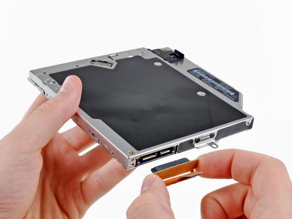
    • Grab the optical drive cable by its connector and pull it away from the body of the hard drive.

    • Pulling on anything but the connector may damage the optical drive cable.

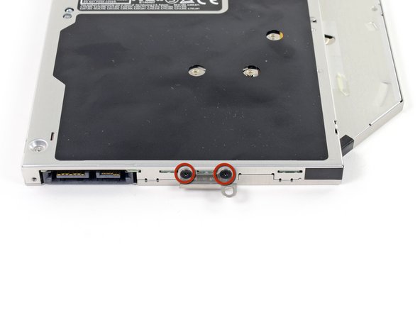
    • Remove the two black Phillips #0 screws securing the small metal mounting bracket. Transfer this bracket to your new optical drive or hard drive enclosure.

  14. : 手順 14、 1の画像 1
    • Bluetoothボードを光学ドライブ側面に固定している、2.2mmプラスネジを2本外します。

  15. : 手順 15、 1の画像 1
    • 光学ドライブからBluetoothボードを取り外します。

    • 光学ドライブが残ります。

  16. , デュアルハードドライブ: 手順 16、 2の画像 1 , デュアルハードドライブ: 手順 16、 2の画像 2
    • プラスチックのスペーサーを光学ベイドライブの筐体からどちらかの側に付けられたクリップを押し込み、持ち上げて外します。

  17. : 手順 17、 3の画像 1 : 手順 17、 3の画像 2 : 手順 17、 3の画像 3
    • ハードドライブコネクタは筐体に取り付ける前に、正面が下向き担っているか確認してください。

    • 丁寧にハードドライブを筐体のハードドライブスロットに取り付けます。

    • 片手でしっかりと筐体を取り付ける位置に固定しながら、もう一方の手でハードドライブを筐体のコネクタに押し込んでください。

  18. : 手順 18、 2の画像 1 : 手順 18、 2の画像 2
    • ハードドライブが装着できたら、ハードドライブを筐体の下部に向かって押さえ込みながら、プラスチックのスペーサーを挿入します。

  19. : 手順 19、 2の画像 1 : 手順 19、 2の画像 2
    • 筐体にドライブを固定している#1プラスネジを2本外します。

  20. : 手順 20、 1の画像 1
    • 光学ドライブのブラケットを新しい筐体に#0のプラスネジを2本取り付けます。

    • オリジナルの光学ドライブから外したケーブルは光学ベイドライブの筐体に取り付けてください。

  21. : 手順 21、 3の画像 1 : 手順 21、 3の画像 2 : 手順 21、 3の画像 3
    • ハードドライブをまだ捨てないでください!SATA光学ドライブUSBケーブルがあれば、外付けで光学ドライブをまだ使用することができます。

    • ケーブルのSATAコネクタをドライブの端子に注意しながら接続します。

    • USBコネクタをラップトップに接続して、光学ドライブを使用できる状態にします。

ゴール

68 の人々がこのガイドを完成させました。

作成者

9人の作成者と共同で作成されました。

Andrew Optimus Goldheart

メンバー登録日: 10/17/09

502,710 ポイント

407のガイドは作成済み

チーム

iFixit iFixit人のメンバー

Staff

135 メンバー

16,731のガイドは作成済み

8 件のコメント

I went through these steps. I dint really have any trouble but now my computer won't turn back on. I have a fair bit of experience opening macbook pros, but I can't figure out what happened. I retrace the steps and look through everything but I can't see why it won't turn on. Any thing I can test? Any help?

signupjordanmathis - 返信

I was able to use the original HDD for Time Machine backups and put a SSD in the original HDD spot, which is a great setup. Of course, I have backups going to a Time Capsule too. The only thing with my model MBP (mid-2011) is that I only get 3 Gigabit speeds, which isn't a huge deal since I'm mainly using the extra space for backups. I really like that I don't have to hear the DVD drive winding up and making spinning noises when I boot up anymore.

mtlangr - 返信

When these steps are completed, I should be able to turn the machine on and it just work? No formatting or configuration needed?

David - 返信

I just installed a SATA III SSD (Samsung EVO 850 1 TB) into my MBP late 2011 17” with the Highfine data doubler. It works like a clock so far - it’s been a week of booting from the optical drive at SATA III speeds. All discussions say this is impossible. It’s not and I’m getting 450 MB/s write and 500 MB/s read. It’s a miracle!

The caddy was $8.99 on Amazon

Erick McWayne - 返信

Fantástico!!! I followed The Steps …. Very easy. Thank you

vilamoura2016 - 返信

コメントを追加

統計データ:

過去 24時間: 2

過去 7 日: 12

過去 30 日: 44

今までの合計 65,513