メインコンテンツにスキップ

このバージョンは誤った内容を含んでいる可能性があります。最新の承認済みスナップショットに切り替えてください。

必要な工具と部品

  1. この手順は未翻訳です。 翻訳を手伝う。

    : 手順 1、 2の画像 1 : 手順 1、 2の画像 2
    • Power down your Mac mini, disconnect all of the cables, and flip it over.

    • Insert the Jimmy into the crack between the aluminum top housing and the plastic lower housing.

    • The Jimmy should reach a stop about 3/8" down.

  2. この手順は未翻訳です。 翻訳を手伝う。

    : 手順 2、 3の画像 1 : 手順 2、 3の画像 2 : 手順 2、 3の画像 3
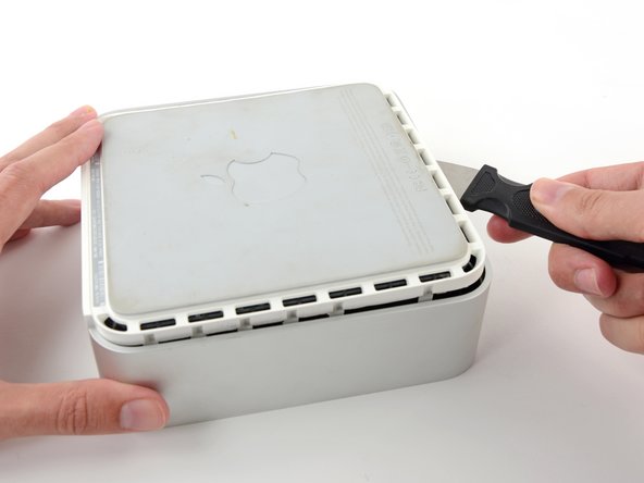
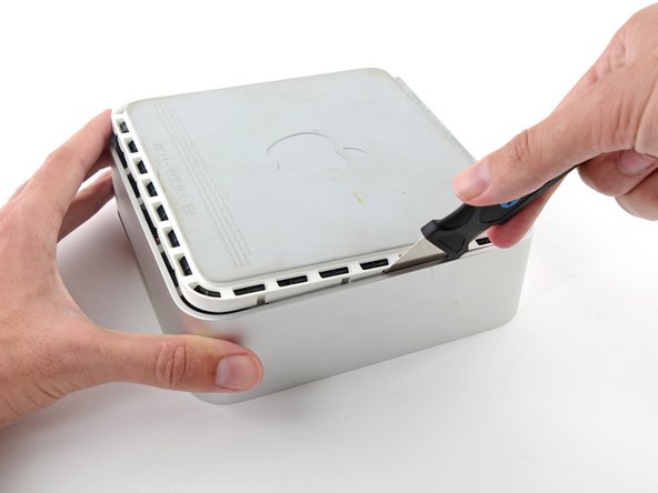
    • Gently bend the Jimmy outwards to pry the crack open a little larger and lift the lower housing up a small amount.

    • There are several plastic clips on the lower housing that fit into a channel in the aluminum top housing. Your goal is to use the Jimmy to push these clips inward enough to free them from the channel, while gently pulling up on the lower housing.

  3. この手順は未翻訳です。 翻訳を手伝う。

    : 手順 3、 2の画像 1 : 手順 3、 2の画像 2
    • Once you have the first side free, rotate the Mac mini and start prying up on the front edge.

    • Use the same prying motion to both bend the clips inward and lift the lower housing up out of the top housing.

  4. この手順は未翻訳です。 翻訳を手伝う。

    : 手順 4、 2の画像 1 : 手順 4、 2の画像 2
    • You may need to move the Jimmy along the edge to pry up all of the clips. Be patient and do a little bit at a time.

  5. この手順は未翻訳です。 翻訳を手伝う。

    : 手順 5、 2の画像 1 : 手順 5、 2の画像 2
    • Keep working around the perimeter, freeing the clips along the final edge.

  6. この手順は未翻訳です。 翻訳を手伝う。

    : 手順 6、 2の画像 1 : 手順 6、 2の画像 2
    • Flip the Mac mini back over and lift the top housing off of the lower housing.

  7. この手順は未翻訳です。 翻訳を手伝う。

    : 手順 7、 3の画像 1 : 手順 7、 3の画像 2 : 手順 7、 3の画像 3
    • Later in this guide you will remove several recessed Phillips screws. Bit drivers are generally too large to fit in the recesses, so be sure to have a thin shafted Phillips screwdriver on hand.

    • First remove the AirPort antenna (the larger of the two), located near the power button.

    • Slightly squeeze the two retaining arms toward each other and lift the AirPort antenna off its post.

    • Squeezing the two posts excessively will surely break them off the internal frame. Work delicately.

    • During reinstallation, you will have to slightly squeeze the two posts together so they fit into the openings on the AirPort antenna board.

  8. この手順は未翻訳です。 翻訳を手伝う。

    : 手順 8、 2の画像 1 : 手順 8、 2の画像 2
    • Use the tip of a spudger to slightly lift the left side of the ZIF cable lock up from its socket.

    • The ZIF cable lock will lift about 1 mm and stop. Do not try to completely remove the ZIF cable lock.

  9. この手順は未翻訳です。 翻訳を手伝う。

    : 手順 9、 1の画像 1
    • Lift the audio board ribbon cable up out of its socket.

    • If it refuses to lift from its socket, the ZIF cable lock is not fully released. Make sure it is evenly lifted about 1 mm from the socket on the interconnect board.

  10. この手順は未翻訳です。 翻訳を手伝う。

    : 手順 10、 2の画像 1 : 手順 10、 2の画像 2
    • Rotate the mini so that the SuperDrive slot loading mechanism is facing you.

    • Use a pair of tweezers to lift the hard drive thermal sensor cable connector up off its socket on the logic board.

    • Use tweezers to grab the connector (as seen in the picture), not the wires.

    • The connector is located under the optical drive opening, next to the PRAM battery.

  11. この手順は未翻訳です。 翻訳を手伝う。

    : 手順 11、 2の画像 1 : 手順 11、 2の画像 2
    • In the next few steps, you will remove the four Phillips screws securing the internal frame to the bottom case. Included in each step is an overview picture showing the general location and a closeup showing the actual screw.

    • Remove the recessed Phillips screw near the power button securing the internal frame to the bottom housing.

  12. この手順は未翻訳です。 翻訳を手伝う。

    : 手順 12、 2の画像 1 : 手順 12、 2の画像 2
    • Remove the recessed Phillips screw near the sleep light securing the internal frame to the bottom housing.

    • This screw is the longest of the four screws securing the internal frame to the bottom case.

  13. この手順は未翻訳です。 翻訳を手伝う。

    : 手順 13、 2の画像 1 : 手順 13、 2の画像 2
    • Remove the Phillips screw from the internal frame near the Bluetooth antenna.

  14. この手順は未翻訳です。 翻訳を手伝う。

    : 手順 14、 2の画像 1 : 手順 14、 2の画像 2
    • Remove the Phillips screw near the audio ports securing the internal frame to the bottom case.

  15. この手順は未翻訳です。 翻訳を手伝う。

    : 手順 15、 2の画像 1 : 手順 15、 2の画像 2
    • Gently lift the internal frame up from the bottom housing, minding the AirPort antenna and any other cables that may get caught.

    • It may be necessary to pull up near the interconnect board to separate it from the logic board.

  16. この手順は未翻訳です。 翻訳を手伝う。

    : 手順 16、 1の画像 1
    • The Bluetooth antenna is removed by simply lifting it up off the internal frame.

    • Remove the Bluetooth antenna from the internal frame by pushing up on both sides of the board as close to the center post as possible.

    • This may require a bit of force.

  17. この手順は未翻訳です。 翻訳を手伝う。

    : 手順 17、 1の画像 1
    • Remove the two Phillips screws securing the optical drive to the internal frame.

  18. この手順は未翻訳です。 翻訳を手伝う。

    : 手順 18、 1の画像 1
    • Turn the mini 180 degrees and remove the two Phillips screws securing the optical drive to the internal frame on the other side.

  19. この手順は未翻訳です。 翻訳を手伝う。

    : 手順 19、 1の画像 1
    • Remove the two Phillips screws securing the interconnect board to the optical drive.

  20. この手順は未翻訳です。 翻訳を手伝う。

    : 手順 20、 1の画像 1
    • Use the flat end of a spudger to separate the interconnect board from the optical drive.

  21. この手順は未翻訳です。 翻訳を手伝う。

    : 手順 21、 1の画像 1
    • Lift the optical drive out of the internal frame.

  22. , デュアルハードドライブ: 手順 22、 2の画像 1 , デュアルハードドライブ: 手順 22、 2の画像 2
    • プラスチックのスペーサーを光学ベイドライブの筐体からどちらかの側に付けられたクリップを押し込み、持ち上げて外します。

  23. : 手順 23、 3の画像 1 : 手順 23、 3の画像 2 : 手順 23、 3の画像 3
    • ハードドライブコネクタは筐体に取り付ける前に、正面が下向き担っているか確認してください。

    • 丁寧にハードドライブを筐体のハードドライブスロットに取り付けます。

    • 片手でしっかりと筐体を取り付ける位置に固定しながら、もう一方の手でハードドライブを筐体のコネクタに押し込んでください。

  24. : 手順 24、 2の画像 1 : 手順 24、 2の画像 2
    • ハードドライブが装着できたら、ハードドライブを筐体の下部に向かって押さえ込みながら、プラスチックのスペーサーを挿入します。

  25. : 手順 25、 2の画像 1 : 手順 25、 2の画像 2
    • 筐体にドライブを固定している#1プラスネジを2本外します。

  26. : 手順 26、 1の画像 1
    • 光学ドライブのブラケットを新しい筐体に#0のプラスネジを2本取り付けます。

    • オリジナルの光学ドライブから外したケーブルは光学ベイドライブの筐体に取り付けてください。

  27. : 手順 27、 3の画像 1 : 手順 27、 3の画像 2 : 手順 27、 3の画像 3
    • ハードドライブをまだ捨てないでください!SATA光学ドライブUSBケーブルがあれば、外付けで光学ドライブをまだ使用することができます。

    • ケーブルのSATAコネクタをドライブの端子に注意しながら接続します。

    • USBコネクタをラップトップに接続して、光学ドライブを使用できる状態にします。

ゴール

28 の人々がこのガイドを完成させました。

作成者

3人の作成者と共同で作成されました。

Brittany McCrigler

メンバー登録日: 03/05/12

89,017 ポイント

131のガイドは作成済み

チーム

iFixit iFixit人のメンバー

Staff

135 メンバー

16,817のガイドは作成済み

6 件のコメント

Is there any drivers or anything that needs to be done on the Mac itself to install this hard drive? Can you use this hard drive to install applications onto as well?

Nathan - 返信

Here's something important to be aware of. DVD Player will not function without a physical dvd drive installed. This is even if you use DVD image files, which I do. The explanation I got is that without that optical drive DVD Player can't check regions. If you want to watch DVDs on your mac mini, even DVD image files, don't remove the optical drive.

Bob Church - 返信

Or, if you want to play dvd files just use vlc player... if vlc can't play it, it can't be played.

cort -

Just added a 500 gig HD I had laying around to a 2007 Mac Mini I got on eBay.....worked like a charm. Thanks iFixit!

Alexsander Jevtich - 返信

although my optical bay hard drive enclosure did not use or have the bracket shown above with two Phillips #0 screws. And the hard drive had a different attachment system. The screws did not come in from the bottom. They came in from the side....no matter still a great solution.

Alexsander Jevtich - 返信

コメントを追加

統計データ:

過去 24時間: 3

過去 7 日: 11

過去 30 日: 47

今までの合計 35,962