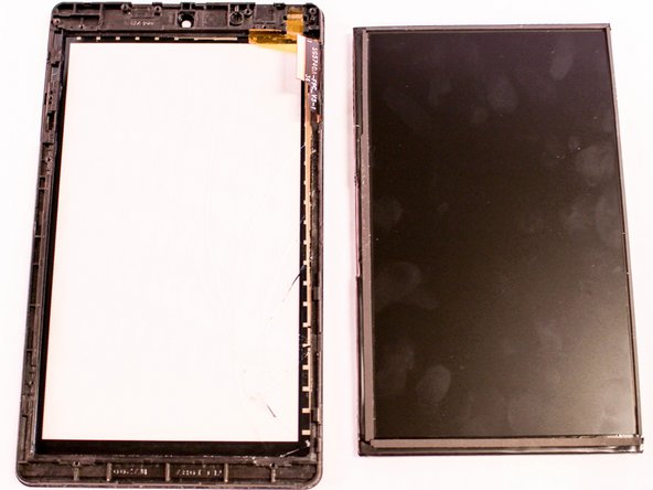
メインコンテンツにスキップ

Insignia Flex 7 Screen Replacement

必要な工具と部品

  1. Insignia Flex 7 Screen Replacement, Battery: 手順 1、 3の画像 1 Insignia Flex 7 Screen Replacement, Battery: 手順 1、 3の画像 2 Insignia Flex 7 Screen Replacement, Battery: 手順 1、 3の画像 3
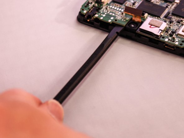
    • Insert the edge of the plastic opener into the grove between the screen and back cover around the perimeter of the device.

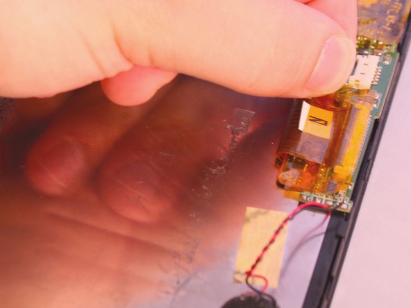
    • Then using a gentle prying motion, create a gap large enough to use your fingers to separate the two halves.

  2. Insignia Flex 7 Screen Replacement: 手順 2、 2の画像 1 Insignia Flex 7 Screen Replacement: 手順 2、 2の画像 2
    • Place the tip of the spudger on each side of the battery's electrical connector.

    • Then using a gentle match-striking motion, loosen both sides of the battery's electrical connector.

  3. Insignia Flex 7 Screen Replacement: 手順 3、 3の画像 1 Insignia Flex 7 Screen Replacement: 手順 3、 3の画像 2 Insignia Flex 7 Screen Replacement: 手順 3、 3の画像 3
    • Insert the flat end of the spudger under one side of the battery.

    • Then using a gentle prying and sliding motion, separate the battery from the case. There are two lengthwise strips of glue holding it down.

    • Repeat the process for the other side of the battery.

  4. Insignia Flex 7 Screen Replacement, Screen: 手順 4、 2の画像 1 Insignia Flex 7 Screen Replacement, Screen: 手順 4、 2の画像 2
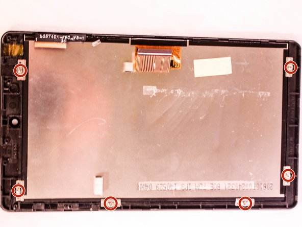
    • Locate the three ribbon cables connecting components to the motherboard. The connections are covered with orange shielding tape. Peel the tape off the connectors and reserve for reassembly.

  5. Insignia Flex 7 Screen Replacement: 手順 5、 3の画像 1 Insignia Flex 7 Screen Replacement: 手順 5、 3の画像 2 Insignia Flex 7 Screen Replacement: 手順 5、 3の画像 3
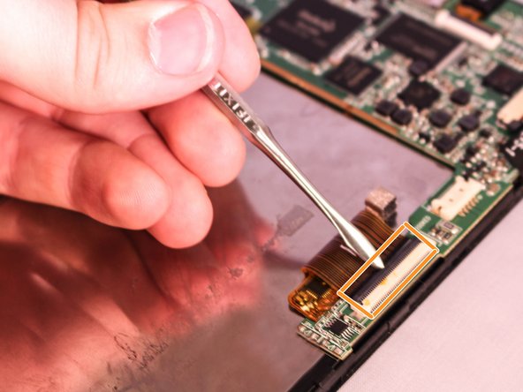
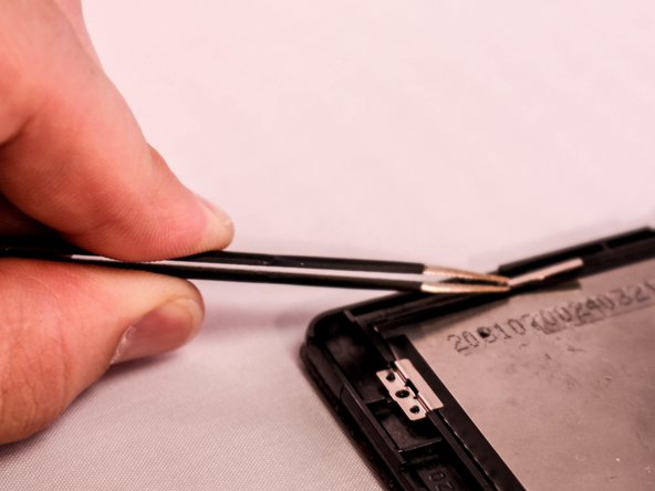
    • Each Zero Insertion Force or ZIF connector has a latch which holds the ribbon cable in place. The camera cable (a) and the LCD display cable (b) have a latch that lifts as shown in the illustration. Use a spudger to gently lift the latch to release the cable.

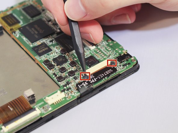
    • The touchscreen cable (c) has a sliding latch on each side of the connector. Use a spudger to carefully slide the latch on each side as shown to release the cable.

  6. Insignia Flex 7 Screen Replacement: 手順 6、 3の画像 1 Insignia Flex 7 Screen Replacement: 手順 6、 3の画像 2 Insignia Flex 7 Screen Replacement: 手順 6、 3の画像 3
    • Using a Phillips #000 screwdriver, remove the six 4.8mm screws holding the motherboard to the case.

    • Using the spudger lift the motherboard from the case.

  7. Insignia Flex 7 Screen Replacement: 手順 7、 3の画像 1 Insignia Flex 7 Screen Replacement: 手順 7、 3の画像 2 Insignia Flex 7 Screen Replacement: 手順 7、 3の画像 3
    • After you have removed the motherboard, use a Phillips #000 screwdriver to unscrew the six 2.9mm screws holding the LCD display to the screen. Using the twizzers remove the clips from the screen.

  8. Insignia Flex 7 Screen Replacement: 手順 8、 2の画像 1 Insignia Flex 7 Screen Replacement: 手順 8、 2の画像 2
    • Using your fingers separate the screen from the LCD display.

終わりに

To reassemble your device, follow these instructions in reverse order.

2 の人々がこのガイドを完成させました。

作成者

3人の作成者と共同で作成されました。

Mariana Gomez

メンバー登録日: 09/28/15

237 ポイント

1ガイドが承認済み

チーム

Eastern Washington University, Team 1-6, Matresse Fall 2015 Eastern Washington University, Team 1-6, Matresse Fall 2015人のメンバー

EWU-MATRESSE-F15S1G6

4 メンバー

10のガイドは作成済み

0 件のコメント

コメントを追加

統計データ:

過去 24時間: 0

過去 7 日: 0

過去 30 日: 2

今までの合計 744