この修理ガイドは変更されています。最新の未承認バージョンに切り替えます。
はじめに
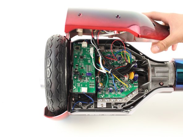
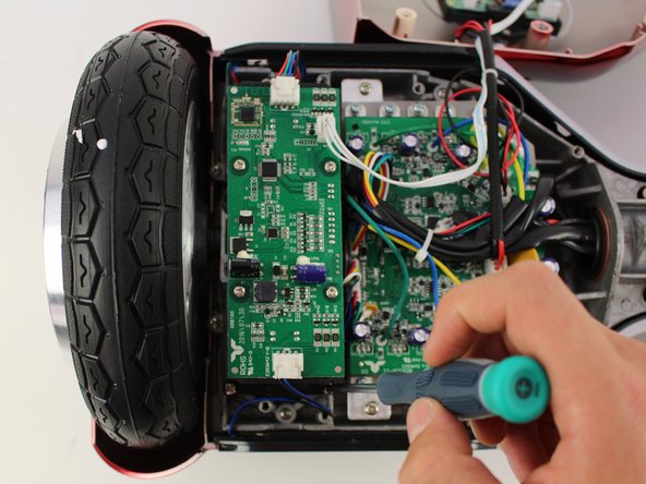
Is one side of your Hover-1 Horizon unresponsive? This is a guide to show you how to replace the left gyroscope board, the most likely culprit to your problem. This guide requires a Phillips #2 and a Phillips #1 screwdriver.
必要な工具と部品
-
-
-
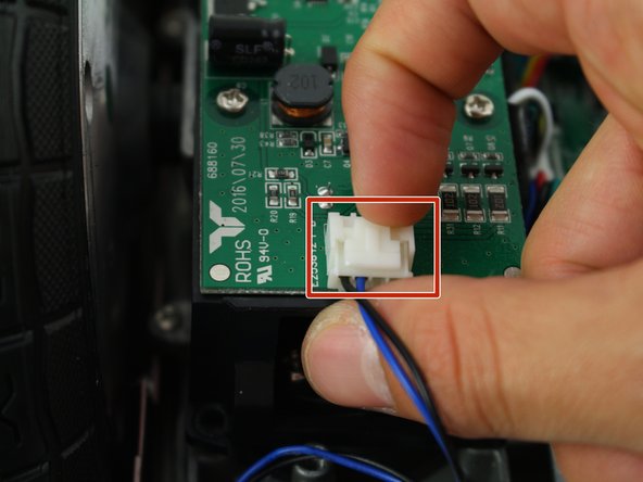
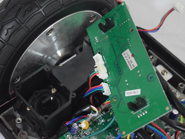
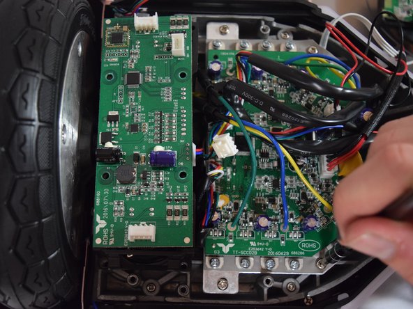
Remove the two connectors on either side of the board by lifting the tab and pulling out.
-
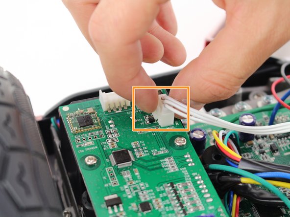
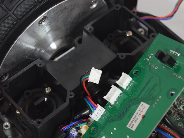
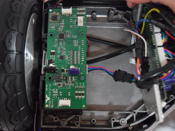
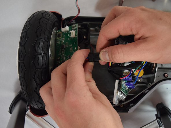
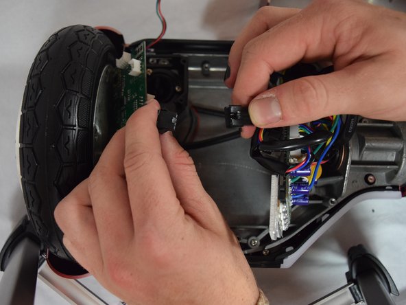
Remove the connector in the middle of the board by squeezing the tab and pulling up.
-


To reassemble your device, follow these instructions in reverse order.
To reassemble your device, follow these instructions in reverse order.
ある他の人がこのガイドを完成しました。
チーム

Cal Poly, Team S13-G6, White Fall 2018 Cal Poly, Team S13-G6, White Fall 2018人のメンバー
CPSU-WHITE-F18S13G6
4 メンバー
6のガイドは作成済み