この修理ガイドは変更されています。最新の未承認バージョンに切り替えます。
はじめに
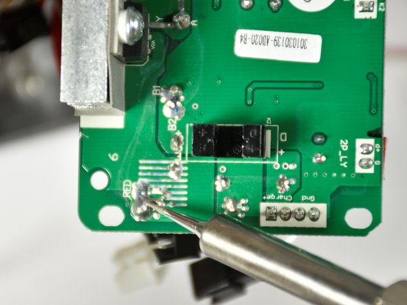
You will need a Phillips #2 screwdriver and a soldering iron.
必要な工具と部品
-
-
Flip the Hover-1 Chrome upside down.
-
Use a Phillips #2 screwdriver to remove the fourteen 14 mm screws from the bottom of the Hover-1.
-
Break the two black tape circles, and remove the two 15 mm Phillips screws underneath.
-
-
-
-
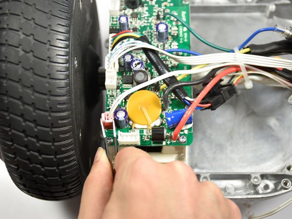
Disconnect the speaker cable.
-
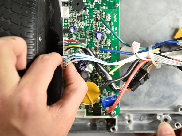
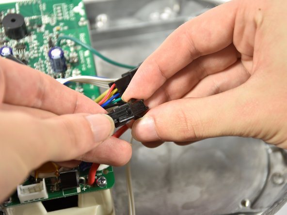
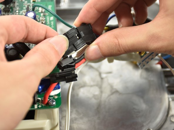
Disconnect the cable that travels to the other sensor board.
-


To reassemble your device, follow these instructions in reverse order.
To reassemble your device, follow these instructions in reverse order.
チーム

Cal Poly, Team S4-G1, White Fall 2018 Cal Poly, Team S4-G1, White Fall 2018人のメンバー
CPSU-WHITE-F18S4G1
4 メンバー
6のガイドは作成済み