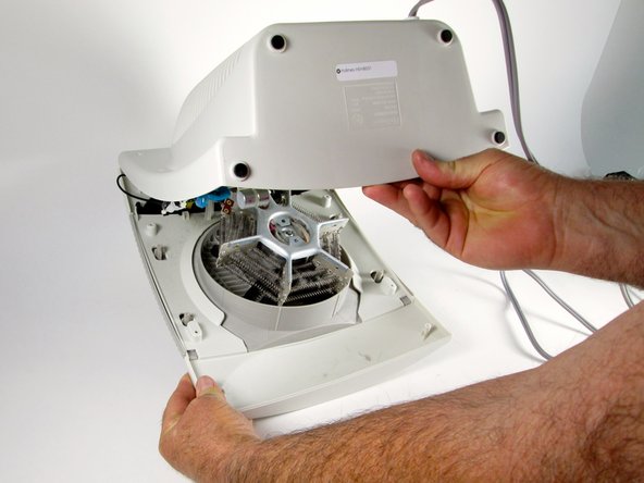
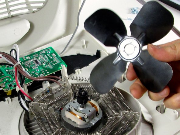
メインコンテンツにスキップ

Holmes HEH8031 Fan Blade Assembly Replacement

必要な工具と部品

  1. Holmes HEH8031 Fan Blade Assembly Replacement, Fan Blade Assembly: 手順 1、 2の画像 1 Holmes HEH8031 Fan Blade Assembly Replacement, Fan Blade Assembly: 手順 1、 2の画像 2
    • Identify that you have the Holmes HEH8031 heater. The model number is on the bottom of the unit.

  2. Holmes HEH8031 Fan Blade Assembly Replacement: 手順 2、 1の画像 1
    • Place the heater so the rear housing is facing you.

    • Remove the eight (8) 1 cm coarse-threaded screws around the perimeter.

    • Remove the two (2) 7 mm machine screws in the center.

  3. Holmes HEH8031 Fan Blade Assembly Replacement: 手順 3、 3の画像 1 Holmes HEH8031 Fan Blade Assembly Replacement: 手順 3、 3の画像 2 Holmes HEH8031 Fan Blade Assembly Replacement: 手順 3、 3の画像 3
    • Using your fingers, pry bottom corner of housing open from bottom to top.

    • Wiring remains connected at the top of the front and rear of the housing. Don't pull too hard or you will disconnect the wires.

    • Fan and rotor assembly are not connected to the housing. They will be loose.

  4. Holmes HEH8031 Fan Blade Assembly Replacement: 手順 4、 2の画像 1 Holmes HEH8031 Fan Blade Assembly Replacement: 手順 4、 2の画像 2
    • Turn the fan blade assembly over so blades are facing up.

    • Locate the four (4) metal tabs that connect the blade assembly to the rotor.

  5. Holmes HEH8031 Fan Blade Assembly Replacement: 手順 5、 2の画像 1 Holmes HEH8031 Fan Blade Assembly Replacement: 手順 5、 2の画像 2
    • Using the pointed metal spudger, bend each of the four (4) metal tabs toward the rotor shaft.

    • Bend tabs only far enough to clear the blade assembly so they can be easily bent back later to reattach the new blade assembly.

  6. Holmes HEH8031 Fan Blade Assembly Replacement, Remove blade assembly: 手順 6、 3の画像 1 Holmes HEH8031 Fan Blade Assembly Replacement, Remove blade assembly: 手順 6、 3の画像 2 Holmes HEH8031 Fan Blade Assembly Replacement, Remove blade assembly: 手順 6、 3の画像 3
    • Lift the blade assembly off the rotor shaft.

    • You may need to wiggle the blade assembly slightly to free it from the rotor.

    • When reassembling the unit, you must replace the two (2) 7 mm machine screws that connect the rotor assembly to the housing before replacing the coarse-threaded screws. Aligning the 1 cm machine screws may take some finesse.

終わりに

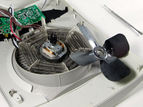
To reassemble your device, follow these instructions in reverse order.

作成者

3人の作成者と共同で作成されました。

Corinne Renguette

メンバー登録日: 05/21/15

152 ポイント

1ガイドが承認済み

チーム

iFixit, Team 1-1, Gismondi Spring 2016 iFixit, Team 1-1, Gismondi Spring 2016人のメンバー

FIX-GISMONDI-S16S1G1

2 メンバー

2のガイドは作成済み

0 件のコメント

コメントを追加

統計データ:

過去 24時間: 0

過去 7 日: 2

過去 30 日: 6

今までの合計 674