メインコンテンツにスキップ

このバージョンは誤った内容を含んでいる可能性があります。最新の承認済みスナップショットに切り替えてください。

必要な工具と部品

  1. この手順は未翻訳です。 翻訳を手伝う。

    : 手順 1、 1の画像 1
    • Using the PH#00 screwdriver, remove the two 0.145 inch Phillips head screws.

    • The screws are located on the bottom face of the device, near the power and volume controls.

  2. この手順は未翻訳です。 翻訳を手伝う。

    : 手順 2、 1の画像 1
    • Place the small suction cup on your screen.

    • Moisturize the bottom of the suction cup to ensure a proper seal.

    • If the screen is cracked, the suction cup may not seal correctly; too much pressure may crack or damage the screen.

  3. この手順は未翻訳です。 翻訳を手伝う。

    : 手順 3、 1の画像 1
    • Insert the plastic opening tool between the screen cover and rear cover of the tablet.

    • Grasp the small suction cup.

  4. この手順は未翻訳です。 翻訳を手伝う。

    : 手順 4、 2の画像 1 : 手順 4、 2の画像 2
    • Slide the plastic opening tool along device edge to separate the screen cover from the rear cover.

    • Pull upward on the small suction cup handle while sliding the opening tool.

    • When sliding the plastic opening tool, avoid sliding the tool too far into the cover. This could damage the speaker connector on the back cover.

  5. この手順は未翻訳です。 翻訳を手伝う。

    : 手順 5、 2の画像 1 : 手順 5、 2の画像 2
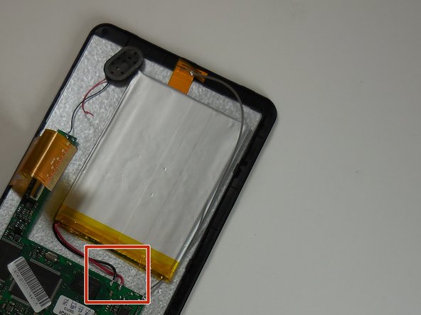
    • Use the plastic opening tool to remove the speaker from the rear cover.

    • The speaker is held in place with adhesive and is easily removed.

    • Do not pull on the speaker wires. This could damage the soldering connections.

  6. この手順は未翻訳です。 翻訳を手伝う。

    : 手順 6、 1の画像 1
    • Once the speaker is disconnected, the cover removal is complete.

  7. この手順は未翻訳です。 翻訳を手伝う。

    : 手順 7、 2の画像 1 : 手順 7、 2の画像 2
    • Remove the black placement tape from the battery.

    • Find the two battery solder connections on the circuit board.

  8. この手順は未翻訳です。 翻訳を手伝う。

    : 手順 8、 1の画像 1
    • Remove the red and black battery wires from the circuit board with the solder removal tool.

  9. この手順は未翻訳です。 翻訳を手伝う。

    : 手順 9、 1の画像 1
    • Solder the new battery wire connectors to the circuit board.

    • The battery wires must be installed with the red wire on the left and black wire on the right.

ゴール

ある他の人がこのガイドを完成しました。

作成者

4人の作成者と共同で作成されました。

Jeffrey

メンバー登録日: 03/11/15

766 ポイント

5のガイドは作成済み

チーム

Colorado Springs, Team 5-6, Panko Spring 2015 Colorado Springs, Team 5-6, Panko Spring 2015人のメンバー

UCCS-PANKO-S15S5G6

3 メンバー

10のガイドは作成済み

0 件のコメント

コメントを追加

統計データ:

過去 24時間: 0

過去 7 日: 0

過去 30 日: 4

今までの合計 4,269