メインコンテンツにスキップ

このバージョンは誤った内容を含んでいる可能性があります。最新の承認済みスナップショットに切り替えてください。

必要な工具と部品

  1. この手順は未翻訳です。 翻訳を手伝う。

    : 手順 1、 2の画像 1 : 手順 1、 2の画像 2
    • Unplug your device before proceeding with disassembly.

    • On the back of the press, remove the locking washer by prying upwards with the nylon or metal spudger tool.

    • Repeat for the other washer across from the first one.

  2. この手順は未翻訳です。 翻訳を手伝う。

    : 手順 2、 2の画像 1 : 手順 2、 2の画像 2
    • Using any long, thin object, push the 43mm bolt from the inside towards the outside to expose the end of the bolt.

    • Pull the end of the bolt out to completely remove it.

    • Repeat for the second bolt.

  3. この手順は未翻訳です。 翻訳を手伝う。

    : 手順 3、 2の画像 1 : 手順 3、 2の画像 2
    • Using the 4.0mm Allen Wrench, unscrew the two 26mm bolts connecting the handle to the upper heating element housing on both sides.

  4. この手順は未翻訳です。 翻訳を手伝う。

    : 手順 4、 1の画像 1
    • Unscrew the locking knob all the way to remove it.

  5. この手順は未翻訳です。 翻訳を手伝う。

    : 手順 5、 3の画像 1 : 手順 5、 3の画像 2 : 手順 5、 3の画像 3
    • Slide the locking knob couple down to the base of the handle, then pull up on the free end of the handle. It will easily pop off.

  6. この手順は未翻訳です。 翻訳を手伝う。

    : 手順 6、 1の画像 1
    • Gently separate the heating element housing from the cooking surface by pulling up on the housing and pushing down on the surface.

    • Pulling too far or too hard can break the delicate internal wiring.

  7. この手順は未翻訳です。 翻訳を手伝う。

    : 手順 7、 1の画像 1
    • On the underside of the housing, use the PH2 Screwdriver to remove the single 12mm screw to disconnect the LED tray.

    • The housing can now be completely removed.

    • Place on the side for reassembly.

  8. この手順は未翻訳です。 翻訳を手伝う。

    : 手順 8、 3の画像 1 : 手順 8、 3の画像 2 : 手順 8、 3の画像 3
    • Using the PH2 screwdriver, remove the single 10mm screw on the circular plastic LED tray.

    • Now remove the small plastic T-shaped piece and the plastic tray completely

  9. この手順は未翻訳です。 翻訳を手伝う。

    : 手順 9、 1の画像 1
    • Gently pull off the translucent bulb covers

  10. この手順は未翻訳です。 翻訳を手伝う。

    : 手順 10、 3の画像 1 : 手順 10、 3の画像 2 : 手順 10、 3の画像 3
    • Very gently, slide the white wiring covers down to expose the wiring connectors

  11. この手順は未翻訳です。 翻訳を手伝う。

    : 手順 11、 1の画像 1
    • Refer to this page to brush up on your soldering skills.

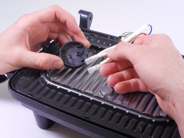
    • The LED can now be removed by desoldering the connector at each wiring junction.

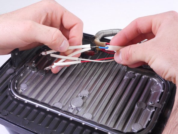
    • The red LED connects to the red wire (positive) and the blue wire (negative, marked in yellow.)

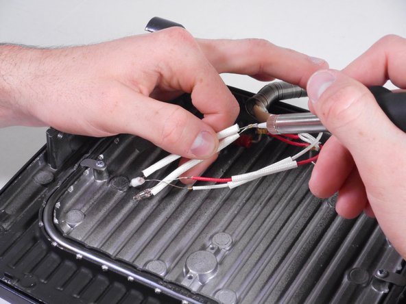
    • The green LED connects to the white wire (Positive) and the blue wire (negative, marked in yellow.)

ゴール

作成者

4人の作成者と共同で作成されました。

Katie Howes

メンバー登録日: 02/01/15

261 ポイント

2のガイドは作成済み

チーム

Cal Poly, Team 6-27, Amido Winter 2015 Cal Poly, Team 6-27, Amido Winter 2015人のメンバー

CPSU-AMIDO-W15S6G27

4 メンバー

6のガイドは作成済み

0 件のコメント

コメントを追加

統計データ:

過去 24時間: 0

過去 7 日: 1

過去 30 日: 5

今までの合計 765