メインコンテンツにスキップ

HTC myTouch 3G Camera Replacement

必要な工具と部品

  1. HTC myTouch 3G Camera Replacement, Remove the Cover: 手順 1、 2の画像 1 HTC myTouch 3G Camera Replacement, Remove the Cover: 手順 1、 2の画像 2
    • Press both thumbs on each side of the upper corners, and apply pressure in a downward motion.

    • While applying downward pressure, slide the back cover down and off the phone.

  2. HTC myTouch 3G Camera Replacement, Remove Battery and SIM Card: 手順 2、 2の画像 1 HTC myTouch 3G Camera Replacement, Remove Battery and SIM Card: 手順 2、 2の画像 2
    • Remove the battery.

    • Remove the SIM card.

  3. HTC myTouch 3G Camera Replacement, Remove SD Card: 手順 3、 1の画像 1
    • Push the SD card in to eject it.

    • Pull the SD card out.

  4. HTC myTouch 3G Camera Replacement, Remove Back Panel Screws: 手順 4、 2の画像 1 HTC myTouch 3G Camera Replacement, Remove Back Panel Screws: 手順 4、 2の画像 2
    • Remove the four 6 mm T5 Torx screws from the four corners on the back of the phone.

    • Remove the two 4 mm T5 Torx screws from the middle of the back of the phone.

  5. HTC myTouch 3G Camera Replacement, Access the Motherboard: 手順 5、 2の画像 1 HTC myTouch 3G Camera Replacement, Access the Motherboard: 手順 5、 2の画像 2
    • Pull out the antenna cover to access the motherboard.

  6. HTC myTouch 3G Camera Replacement, Dislodge the Back Plate: 手順 6、 2の画像 1 HTC myTouch 3G Camera Replacement, Dislodge the Back Plate: 手順 6、 2の画像 2
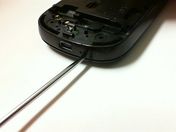
    • Insert a spudger into the gap between the frame and cover. Push downward with the spudger to separate the back plate from the phone.

    • With the spudger in the gap between the frame and cover, move the spudger around the edge of the of the phone to finish removing the back plate.

  7. HTC myTouch 3G Camera Replacement, Remove Back Screws: 手順 7、 2の画像 1 HTC myTouch 3G Camera Replacement, Remove Back Screws: 手順 7、 2の画像 2
    • Remove the 3 mm Phillips screw located on the side of the bottom left-hand corner of the phone.

    • Remove the 3 mm Phillips screw located on the top right-hand corner of the phone.

    • Do not remove any of the screws located on the actual circuit boards.

  8. HTC myTouch 3G Camera Replacement, Separate the Circuit Board: 手順 8、 3の画像 1 HTC myTouch 3G Camera Replacement, Separate the Circuit Board: 手順 8、 3の画像 2 HTC myTouch 3G Camera Replacement, Separate the Circuit Board: 手順 8、 3の画像 3
    • Place a finger between the circuit board and front cover, and lift the circuit board gently.

    • Separate the circuit board from the front cover and screen to access the ribbon cable holding them together. Detach the ribbon cable.

    • Finish separating the circuit board from the front panel.

  9. HTC myTouch 3G Camera Replacement, Camera: 手順 9、 1の画像 1
    • Turn the device housing the circuit boards over to the side with the mounted camera.

    • Remove the three 3 mm Phillips head screws located on the top circuit board.

  10. HTC myTouch 3G Camera Replacement: 手順 10、 3の画像 1 HTC myTouch 3G Camera Replacement: 手順 10、 3の画像 2 HTC myTouch 3G Camera Replacement: 手順 10、 3の画像 3
    • Locate the ribbon cable on the top circuit board.

    • Use a precision screwdriver to flip open the ribbon cable.

  11. HTC myTouch 3G Camera Replacement: 手順 11、 2の画像 1 HTC myTouch 3G Camera Replacement: 手順 11、 2の画像 2
    • Locate the two wired connections on the top circuit board.

  12. HTC myTouch 3G Camera Replacement: 手順 12、 2の画像 1 HTC myTouch 3G Camera Replacement: 手順 12、 2の画像 2
    • Remove the wired connections by using a squeeze-and-pull action.

  13. HTC myTouch 3G Camera Replacement: 手順 13、 3の画像 1 HTC myTouch 3G Camera Replacement: 手順 13、 3の画像 2 HTC myTouch 3G Camera Replacement: 手順 13、 3の画像 3
    • Slowly lift the circuit board from the left.

    • Continue to flip the circuit board all the way over to the right; it will maintain a connection to the device.

  14. HTC myTouch 3G Camera Replacement: 手順 14、 3の画像 1 HTC myTouch 3G Camera Replacement: 手順 14、 3の画像 2 HTC myTouch 3G Camera Replacement: 手順 14、 3の画像 3
    • The other side of the camera and circuit board should now be exposed.

    • Disconnect the ribbon cable with a precision screwdriver.

    • Remove the faulty camera and install a new one.

終わりに

To reassemble your device, follow these instructions in reverse order.

ある他の人がこのガイドを完成しました。

作成者

10人の作成者と共同で作成されました。

Tony Tran

メンバー登録日: 09/25/12

381 ポイント

3のガイドは作成済み

チーム

Cal Poly, Team 2-9, Propen Fall 2012 Cal Poly, Team 2-9, Propen Fall 2012人のメンバー

CPSU-PROPEN-F12S2G9

3 メンバー

10のガイドは作成済み

0 件のコメント

コメントを追加

統計データ:

過去 24時間: 0

過去 7 日: 0

過去 30 日: 0

今までの合計 1,497