メインコンテンツにスキップ

このバージョンは誤った内容を含んでいる可能性があります。最新の承認済みスナップショットに切り替えてください。

必要な工具と部品

  1. , iOpenerの使用方法: 手順 1、 2の画像 1 , iOpenerの使用方法: 手順 1、 2の画像 2
    • 電子レンジに付着している汚れがiOpenerに付いてしまうことがあるので、使用前に電子レンジの底をきれいに拭き取ってください。

    • iOpenerを電子レンジ中央に置きます。

    • 回転型の電子レンジ:iOpenerが電子レンジのターンテーブルで回転しているか確認してください。iOpenerが作動中に留まってしまうと、熱しすぎや焦げてしまいます。

  2. : 手順 2、 1の画像 1
    • iOpenerを30秒温めます。

    • 修理作業中はiOpenerが冷めてしまいますので、使用毎に電子レンジに30秒入れて温めてからご利用ください。

    • 作業中、iOpenerを温めすぎないようにご注意ください。過熱すると、iOpenerが破裂することがあります。100˚Cを超えるまで加熱しないでください。

    • 膨らんでいる状態のiOpenerは絶対に触らないでください。

    • 適切に温められたiOpenerは約10分間、温かい状態を保ちます。

  3. : 手順 3、 1の画像 1
    • 電子レンジからiOpenerを取り出します。iOpenerの中央は熱くなっているため、両端の平面になっている部分を持ってください。

    • iOpenerは大変熱くなっていることがあります。必要であれば、オーブン用のミトンカバーをご利用ください。

  4. , iOpenerを使った他の温熱方法: 手順 4、 2の画像 1 , iOpenerを使った他の温熱方法: 手順 4、 2の画像 2
    • 電子レンジがない場合は、熱湯の中にiOpener をいれて温める方法もあります。

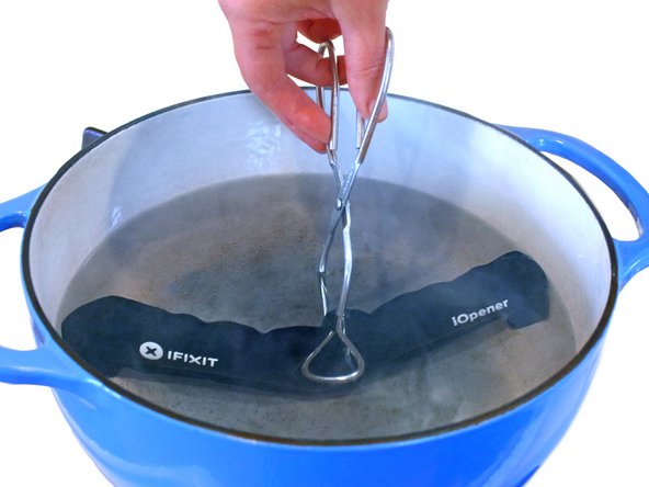
    • 鍋を十分な量のお湯で満たして、iOpener を完全に沈めます。

    • お湯を沸かして熱くなったら火を止めます

    • iOpenerを熱湯の中に約2−3分間沈めます。iOpener全体が完全に浸かっているか確認してください。

    • トングなどを浸かって、温まったiOpenerをお湯から取り出します。

    • タオルでiOpener全体を拭き取ります。

    • iOpenerが非常に熱い場合は、先端のタブを持って火傷をしないようにご注意ください。

    • iOpenerの準備は整いました。iOpenerを再度温める必要がある場合は、お湯を沸騰させて、火を止めてからiOpenerを2-3分間浸してください。

  5. この手順は未翻訳です。 翻訳を手伝う。

    : 手順 5、 1の画像 1
    • Handling it by the tag, place the heated iOpener across the bottom casing.

    • Let the iOpener sit for at least a minute to soften the adhesive beneath the casing.

  6. この手順は未翻訳です。 翻訳を手伝う。

    : 手順 6、 3の画像 1 : 手順 6、 3の画像 2 : 手順 6、 3の画像 3
    • Gently place an opening pick in the corner of the gap between the bottom casing and rear case.

    • Slide the opening pick along the side of the casing, prying it away from the adhesive as you go.

  7. この手順は未翻訳です。 翻訳を手伝う。

    : 手順 7、 1の画像 1
    • Use your fingers to pull the bottom casing off the rest of the phone.

  8. この手順は未翻訳です。 翻訳を手伝う。

    : 手順 8、 2の画像 1 : 手順 8、 2の画像 2
    • Starting at the groove near the headphone jack, use a plastic opening tool to lift the top casing.

  9. この手順は未翻訳です。 翻訳を手伝う。

    : 手順 9、 1の画像 1
    • Use your fingers to pull the top casing off of the rest of the phone.

  10. この手順は未翻訳です。 翻訳を手伝う。

    : 手順 10、 1の画像 1
    • Remove the following screws holding the rear case to the rest of the phone:

    • Two 3.15 mm Phillips #00 screws

    • One 4.15 Torx T5 screw

    • One 4 mm Torx T5 screw

  11. この手順は未翻訳です。 翻訳を手伝う。

    : 手順 11、 3の画像 1 : 手順 11、 3の画像 2 : 手順 11、 3の画像 3
    • Place your fingers on either side of the phone and gently push up on the rear case.

    • It is important to start from the bottom of the phone because the rear case wraps around the front of the phone at the top which makes it impossible to start prying from there.

  12. この手順は未翻訳です。 翻訳を手伝う。

    : 手順 12、 1の画像 1
    • Pull the rear case away from the rest of the phone with your hands.

  13. この手順は未翻訳です。 翻訳を手伝う。

    : 手順 13、 2の画像 1 : 手順 13、 2の画像 2
    • Using the pointed end of a spudger, lift the battery cable and release the connector.

  14. この手順は未翻訳です。 翻訳を手伝う。

    : 手順 14、 2の画像 1 : 手順 14、 2の画像 2
    • Switching to the flat end of the spudger, work your way underneath the battery and peel it away from the adhesive.

  15. この手順は未翻訳です。 翻訳を手伝う。

    : 手順 15、 1の画像 1
    • Remove the battery from the phone.

  16. この手順は未翻訳です。 翻訳を手伝う。

    : 手順 16、 1の画像 1
    • Remove the three 3.15mm Phillips #00 screws from the turquoise case.

  17. この手順は未翻訳です。 翻訳を手伝う。

    : 手順 17、 2の画像 1 : 手順 17、 2の画像 2
    • Using a plastic opening tool, lift the turquoise case from the end near the headphone jack.

  18. この手順は未翻訳です。 翻訳を手伝う。

    : 手順 18、 1の画像 1
    • Remove the turquoise cover from the phone.

  19. この手順は未翻訳です。 翻訳を手伝う。

    : 手順 19、 2の画像 1 : 手順 19、 2の画像 2
    • A camera filter is now free to move, so remove it using tweezers.

  20. この手順は未翻訳です。 翻訳を手伝う。

    : 手順 20、 3の画像 1 : 手順 20、 3の画像 2 : 手順 20、 3の画像 3
    • Use tweezers to lift the yellow polyimide tape that covers the ZIF connectors.

  21. この手順は未翻訳です。 翻訳を手伝う。

    : 手順 21、 2の画像 1 : 手順 21、 2の画像 2
    • Use the pointed end of a spudger to lift the white tab on the largest ZIF connector opposite the USB connector.

  22. この手順は未翻訳です。 翻訳を手伝う。

    : 手順 22、 3の画像 1 : 手順 22、 3の画像 2 : 手順 22、 3の画像 3
    • Use the pointed edge of a spudger to work the ZIF cable out of its connector.

    • To do this, you may have to slowly work both sides until the whole cable is released.

  23. この手順は未翻訳です。 翻訳を手伝う。

    : 手順 23、 1の画像 1
    • Repeat the procedure from steps 19 and 20 to remove the cables from the remaining ZIF connectors.

  24. この手順は未翻訳です。 翻訳を手伝う。

    : 手順 24、 2の画像 1 : 手順 24、 2の画像 2
    • Using the pointed end of the spudger, pop the antenna cable from its connector on the motherboard.

  25. この手順は未翻訳です。 翻訳を手伝う。

    : 手順 25、 1の画像 1
    • Remove the 3.15 mm Phillips #00 screw from the motherboard.

  26. この手順は未翻訳です。 翻訳を手伝う。

    : 手順 26、 2の画像 1 : 手順 26、 2の画像 2
    • Remove the motherboard from the rest of the phone.

  27. この手順は未翻訳です。 翻訳を手伝う。

    : 手順 27、 1の画像 1
    • Remove the plastic casing from the phone assembly.

    • If you have difficulty removing the casing, use the plastic opening tool to gently pry it off.

  28. この手順は未翻訳です。 翻訳を手伝う。

    : 手順 28、 2の画像 1 : 手順 28、 2の画像 2
    • Using the nylon spudger, remove the circuit board from the phone.

    • Use a metal spudger only as a last resort because it can damage the phone.

  29. この手順は未翻訳です。 翻訳を手伝う。

    : 手順 29、 1の画像 1
    • The component denoted in the red box is the vibration motor. Remove the component by desoldering the surface-mount joints.

ゴール

作成者

1人の作成者と共同作成されました。

Adam Redmond

メンバー登録日: 05/16/17

535 ポイント

5のガイドは作成済み

チーム

IUPUI, Team S4-G3, Harley Spring 2017 IUPUI, Team S4-G3, Harley Spring 2017人のメンバー

IUPUI-HARLEY-S17S4G3

3 メンバー

5のガイドは作成済み

0 件のコメント

コメントを追加

統計データ:

過去 24時間: 0

過去 7 日: 3

過去 30 日: 3

今までの合計 208