メインコンテンツにスキップ

HTC OPM9200 Lower Logic Board Prerequisite

必要条件のみ
この修理ガイドは、他のガイドの前提条件として使用されます。それ自体は不完全で、単独で使用されることはありません。

必要な工具と部品

  1. HTC OPM9200 Lower Logic Board Prerequisite, Backplate Removal Prereq: 手順 1、 3の画像 1 HTC OPM9200 Lower Logic Board Prerequisite, Backplate Removal Prereq: 手順 1、 3の画像 2 HTC OPM9200 Lower Logic Board Prerequisite, Backplate Removal Prereq: 手順 1、 3の画像 3
    • Before you proceed, discharge your device battery below 25%. A charged lithium-ion battery can catch fire and/or explode if accidentally punctured.

    • Power off the device.

    • Locate the SD Card/SIM Card cover flap on the left side of the device.

    • Upon opening the cover flap you will find slots for SD Card and the SIM Card. Carefully remove these items if your device has them and set them aside.

    • Lift on the back cover to begin the removal process. Continue removing the back cover by working along the edge. Once removed set aside the back cover.

  2. HTC OPM9200 Lower Logic Board Prerequisite: 手順 2、 1の画像 1
    • Remove the five 3.5mm T4 Torx Screws.

    • Remove the two 4.5mm #00 Phillips screws.

    • Please be aware of the sticker below the battery. Following this guide past this point may void your device's warranty.

  3. HTC OPM9200 Lower Logic Board Prerequisite: 手順 3、 2の画像 1 HTC OPM9200 Lower Logic Board Prerequisite: 手順 3、 2の画像 2
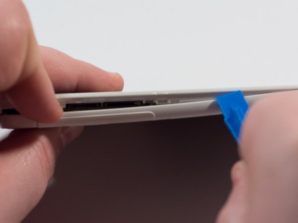
    • Place a plastic opening tool along the seam of the front plate and back plate. Run the opening tool along the seam while prying slightly in order to pop the plastic clips away from the front plate.

    • Once one or two clips have popped away you may begin to use your free hand to apply additional pressure while continuing to apply prying pressure as well with the opening tool.

    • Apply constant but controlled pressure while separating the front from the back. Damage may occur if using excessive pressure while separating the plates along the seam.

  4. HTC OPM9200 Lower Logic Board Prerequisite: 手順 4、 1の画像 1
    • Continue working your way around the seam between the two parts and eventually you will be able to separate the entirety of the backplate revealing the internals of the device.

  5. HTC OPM9200 Lower Logic Board Prerequisite, Battery Removal: 手順 5、 1の画像 1
    • Note the position of the battery connector.

    • We will be prying on the battery shortly which may cause accidental pressure to be place on this connector. Be careful not to damage this connector while removing the battery.

  6. HTC OPM9200 Lower Logic Board Prerequisite: 手順 6、 2の画像 1 HTC OPM9200 Lower Logic Board Prerequisite: 手順 6、 2の画像 2
    • Place the plastic opening tool to the side of the battery and work underneath the battery. Slowly and gently pry the battery away from the device removing the battery from the adhesive underneath.

    • After breaking away one side of the battery from the adhesive strips you can take advantage of the additional leverage by using your hand to break free from the adhesive on the opposite side.

    • You will hear cracking and popping as the battery breaks loose from the adhesive strips underneath. This is normal and to be expected.

  7. HTC OPM9200 Lower Logic Board Prerequisite: 手順 7、 1の画像 1
    • After prying the battery free from the device the connector can be removed by pulling directly up away from the device.

  8. HTC OPM9200 Lower Logic Board Prerequisite, Lower Logic Board Prereq: 手順 8、 1の画像 1
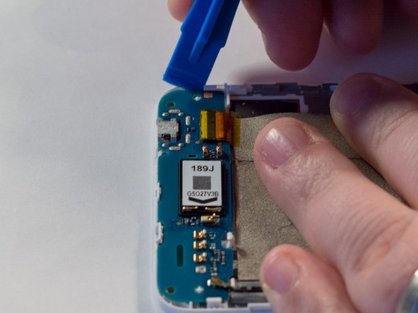
    • Remove the antenna connector from the bottom logic board by using tweezers. Grasp the bottom of the metal connector and pull away towards the top of the connector.

    • The connector should come free easily if done correctly.

  9. HTC OPM9200 Lower Logic Board Prerequisite: 手順 9、 1の画像 1
    • Remove the tape covering the connector that holds the ribbon cable to the lower logic board in place.

    • Use tweezers to pull the ribbon cable free of the connector. Pulling directly away from the connector apply even and constant pressure until the cable slides free.

  10. HTC OPM9200 Lower Logic Board Prerequisite: 手順 10、 2の画像 1 HTC OPM9200 Lower Logic Board Prerequisite: 手順 10、 2の画像 2
    • Note the position of the three plastic clips holding the lower logic board in place.

    • Place the plastic opening tool along one side and slowly begin to pry up. The board will flex slightly allowing it to pass by and free of the plastic clips.

終わりに

To reassemble your device, follow these instructions in reverse order.

作成者

1人の作成者と共同作成されました。

Steve Gilland

メンバー登録日: 01/18/17

1,043 ポイント

10のガイドは作成済み

チーム

Arkansas State University, Team 1-3, Chamberlain Spring 2017 Arkansas State University, Team 1-3, Chamberlain Spring 2017人のメンバー

ARSU-CHAMBERLAIN-S17S1G3

3 メンバー

20のガイドは作成済み

0 件のコメント

コメントを追加

統計データ:

過去 24時間: 0

過去 7 日: 0

過去 30 日: 0

今までの合計 13