メインコンテンツにスキップ

このバージョンは誤った内容を含んでいる可能性があります。最新の承認済みスナップショットに切り替えてください。

必要な工具と部品

  1. この手順は未翻訳です。 翻訳を手伝う。

    : 手順 1、 1の画像 1
    • While sliding the silver release tab up, simultaneously lift the cover up from the left side.

  2. この手順は未翻訳です。 翻訳を手伝う。

    : 手順 2、 1の画像 1
    • Push the tab left to right to remove the cover.

  3. この手順は未翻訳です。 翻訳を手伝う。

    : 手順 3、 1の画像 1
    • Now, lift the battery up and away from the device to remove it.

  4. この手順は未翻訳です。 翻訳を手伝う。

    : 手順 4、 1の画像 1
    • Remove the four silver screws using the T5 Torx Screwdriver (T5 x .25 in).

  5. この手順は未翻訳です。 翻訳を手伝う。

    : 手順 5、 1の画像 1
    • Remove the single black screw that is located beneath the HP sticker with the T5 Torx Screwdriver.

  6. この手順は未翻訳です。 翻訳を手伝う。

    : 手順 6、 2の画像 1 : 手順 6、 2の画像 2
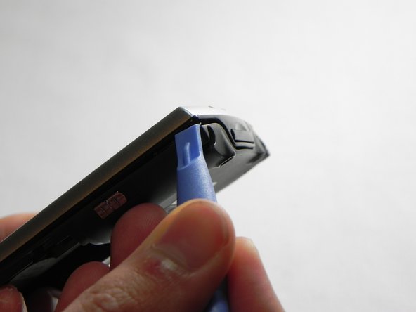
    • Next, use your plastic removal tool to separate the gray back from the black center piece.

    • For better results, start the separation at the corner piece.

  7. この手順は未翻訳です。 翻訳を手伝う。

    : 手順 7、 1の画像 1
    • Remove the back case.

  8. この手順は未翻訳です。 翻訳を手伝う。

    : 手順 8、 1の画像 1
    • Now that the back cover is removed, use the #00 Philips x .17 screwdriver to remove the small screw to the left of the SD card slot.

  9. この手順は未翻訳です。 翻訳を手伝う。

    : 手順 9、 2の画像 1 : 手順 9、 2の画像 2
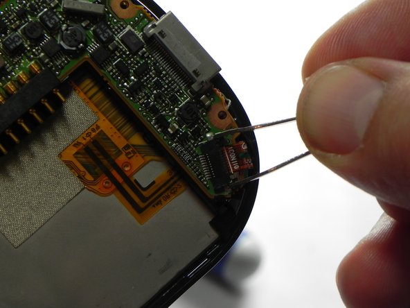
    • Next, unlock and remove the ribbon cable.

    • Using metal tweezers, carefully pull back on both sides of the brown bar unlocking the cable and slipping it out of the connector.

    • The bar, the connector, and the cable are fragile components that are easily broken.

  10. この手順は未翻訳です。 翻訳を手伝う。

    : 手順 10、 2の画像 1 : 手順 10、 2の画像 2
    • Next, remove the wire from the bottom of the mother board.

    • The easiest method is to use metal tweezers and grip the plug closest to the connector.

    • Make sure all the connections are properly disconnected before separation from the motherboard.

  11. この手順は未翻訳です。 翻訳を手伝う。

    : 手順 11、 1の画像 1
    • Next, use a plastic removal tool and separate the silver front case from the black frame.

  12. この手順は未翻訳です。 翻訳を手伝う。

    : 手順 12、 1の画像 1
    • Now that the front cover is removed we will need to disconnect the LCD screen from the mother board. Pull the LCD connection out of the slot to properly disconnect.

  13. この手順は未翻訳です。 翻訳を手伝う。

    : 手順 13、 1の画像 1
    • Next we will need to remove the last wire from the motherboard

    • The easiest method is to grab and pull with metal tweezers near the bottom of the plug near the connector.

  14. この手順は未翻訳です。 翻訳を手伝う。

    : 手順 14、 2の画像 1 : 手順 14、 2の画像 2
    • Finally the mother board can be removed from the center black frame.

ゴール

ある他の人がこのガイドを完成しました。

作成者

5人の作成者と共同で作成されました。

John Pagliero

メンバー登録日: 01/27/11

942 ポイント

7のガイドは作成済み

0 件のコメント

コメントを追加

統計データ:

過去 24時間: 0

過去 7 日: 9

過去 30 日: 15

今までの合計 1,097