メインコンテンツにスキップ

このバージョンは誤った内容を含んでいる可能性があります。最新の承認済みスナップショットに切り替えてください。

必要条件のみ
この修理ガイドは、他のガイドの前提条件として使用されます。それ自体は不完全で、単独で使用されることはありません。

必要な工具と部品

  1. この手順は未翻訳です。 翻訳を手伝う。

    : 手順 1、 1の画像 1
    • In the following steps, you will use a metal spudger to lift the front panel out from the rear case of your TouchPad.

    • The front panel is held in by seven clips (boxed in red) that are lightly anchored to the rear case. When you remove the front panel assembly, you are bound to break either the clips or their supports attached to the rear case. We will update this guide as we find replacement parts or a better method to remove the panel.

    • As you remove the front panel assembly, also be careful not to damage the ambient light sensor (boxed in yellow) or the two antennas (boxed in orange).

  2. この手順は未翻訳です。 翻訳を手伝う。

    : 手順 2、 1の画像 1
    • Insert a flat metal spudger in the gap between the rubber outer ring on the front panel assembly and the black plastic rear case near the USB connector.

    • Pry the front panel assembly up from the rear case, being careful not to damage the LCD or the glass panel.

    • As you work through the following steps, insert your metal spudger and pry the front panel up, but do not try to slide the spudger along the gap you're creating. Always remove your spudger, then insert it at another spot and pry upward.

  3. この手順は未翻訳です。 翻訳を手伝う。

    : 手順 3、 2の画像 1 : 手順 3、 2の画像 2
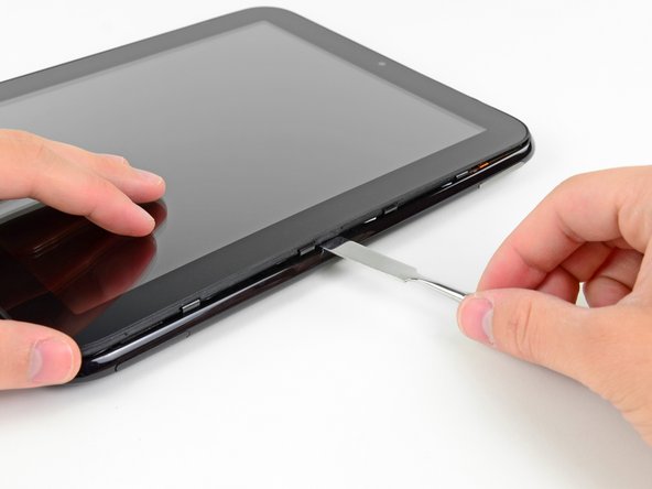
    • As in the previous step, use a spudger to pry the front panel up from the rear case along its long edge on the volume button side of the TouchPad.

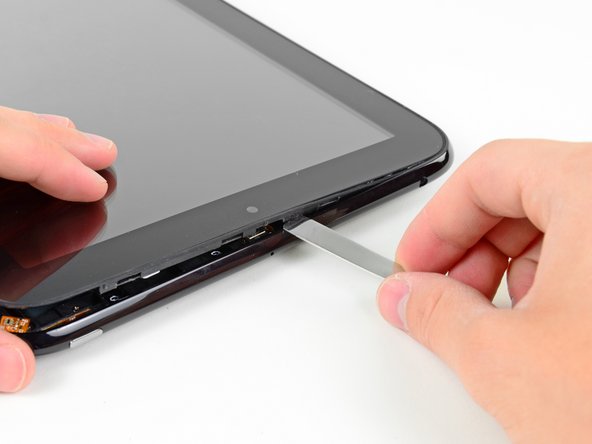
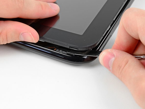
    • Continue to pry the front panel assembly up along the volume button side of the TouchPad until there is a gap between it and the rear case.

  4. この手順は未翻訳です。 翻訳を手伝う。

    : 手順 4、 2の画像 1 : 手順 4、 2の画像 2
    • Pry up the front panel assembly along the top edge of the TouchPad.

    • Be careful not to damage the ambient light sensor or the upper antenna.

  5. この手順は未翻訳です。 翻訳を手伝う。

    : 手順 5、 1の画像 1
    • Pry up the front panel along the edge closest to the home screen button.

  6. この手順は未翻訳です。 翻訳を手伝う。

    : 手順 6、 2の画像 1 : 手順 6、 2の画像 2
    • Before lifting the free side of the front panel up from the rear case, you may need to release it from the plastic retaining clips holding it down.

    • Use your metal spudger to pull the stuck retaining clips away from the edge of the front panel.

  7. この手順は未翻訳です。 翻訳を手伝う。

    : 手順 7、 1の画像 1
    • After freeing the retaining clips, lift the front panel assembly away from the rear case.

    • Do not try to remove the front panel assembly from the TouchPad just yet, as it is still connected to the motherboard.

  8. この手順は未翻訳です。 翻訳を手伝う。

    : 手順 8、 1の画像 1
    • Use the attached black tab to pull the display data cable straight up and out of its socket on the motherboard.

    • Pull the cable upwards and not parallel to the face of the motherboard. Doing otherwise may damage the socket on the motherboard.

    • Take care not to pull on the ribbon that is stuck by adhesive to the bottom of cable you are detaching. It does not need to be disconnected.

  9. この手順は未翻訳です。 翻訳を手伝う。

    : 手順 9、 3の画像 1 : 手順 9、 3の画像 2 : 手順 9、 3の画像 3
    • Use your fingernail to carefully flip up the retaining flaps on the two digitizer ribbon cable ZIF sockets.

    • Be sure you are prying up on the hinged retaining flaps, not the sockets themselves.

    • Pull the digitizer ribbon cable straight out of its two sockets on the motherboard.

  10. この手順は未翻訳です。 翻訳を手伝う。

    : 手順 10、 1の画像 1
    • Remove the front panel assembly from the rear case assembly.

ゴール

作成者

5人の作成者と共同で作成されました。

Andrew Bookholt

586,588 ポイント

619のガイドは作成済み

0 件のコメント

コメントを追加

統計データ:

過去 24時間: 0

過去 7 日: 10

過去 30 日: 13

今までの合計 721