メインコンテンツにスキップ

このバージョンは誤った内容を含んでいる可能性があります。最新の承認済みスナップショットに切り替えてください。

必要な工具と部品

  1. この手順は未翻訳です。 翻訳を手伝う。

    : 手順 1、 2の画像 1 : 手順 1、 2の画像 2
    • Begin your replacement by using a T3 or T4 Torx screwdriver.

    • Remove the two 1.4mm x 3mm Torx Head screws at the top of the device.

  2. この手順は未翻訳です。 翻訳を手伝う。

    : 手順 2、 2の画像 1 : 手順 2、 2の画像 2
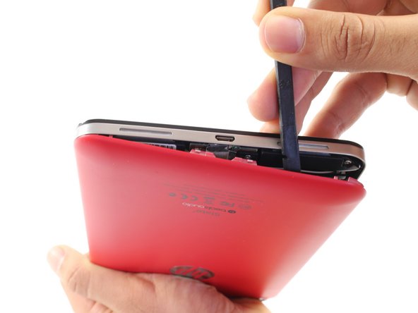
    • With the pointed end of the spudger, remove the thin metal band.

    • It is easiest to remove the metal band through the headphone opening.

  3. この手順は未翻訳です。 翻訳を手伝う。

    : 手順 3、 2の画像 1 : 手順 3、 2の画像 2
    • Using the flat end of the spudger, pry back the rear plastic cover.

    • As you work your way around the edge, several "pop" noises will be made. These noises are caused by the plastic clips coming undone.

  4. この手順は未翻訳です。 翻訳を手伝う。

    : 手順 4、 1の画像 1
    • Remove the rear cover.

  5. この手順は未翻訳です。 翻訳を手伝う。

    : 手順 5、 1の画像 1
    • Locate and remove the yellow tape covering the red and white speaker wires.

  6. この手順は未翻訳です。 翻訳を手伝う。

    : 手順 6、 2の画像 1 : 手順 6、 2の画像 2
    • Using the pointed end of the spudger, push both sides of the speaker wire connector out of its base.

    • Push the same amount on both sides of the connector to avoid jamming or twisting its metal pins.

    • Do not yank or pull on the speaker wires, since they are fragile. Only push on the white connector.

  7. この手順は未翻訳です。 翻訳を手伝う。

    : 手順 7、 1の画像 1
    • Gently pull back the foil covering the gold charging port ribbon.

  8. この手順は未翻訳です。 翻訳を手伝う。

    : 手順 8、 2の画像 1 : 手順 8、 2の画像 2
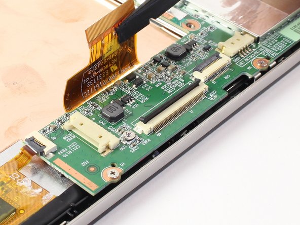
    • Using the flat end of the spudger, lift up the black panel covering the charging port connector.

    • Gently slide the charging port ribbon out from its housing.

    • It may be easier to use the pointed end of the spudger than your fingers.

  9. この手順は未翻訳です。 翻訳を手伝う。

    : 手順 9、 1の画像 1
    • Lift gold charging strip away from the battery.

  10. この手順は未翻訳です。 翻訳を手伝う。

    : 手順 10、 2の画像 1 : 手順 10、 2の画像 2
    • Push the white battery connector out of its housing using the pointed end of the spudger.

  11. この手順は未翻訳です。 翻訳を手伝う。

    : 手順 11、 1の画像 1
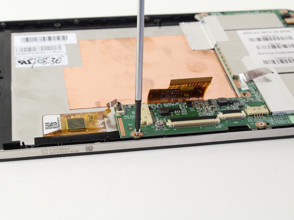
    • Using the #00 Phillips Head screwdriver, remove the 5 screws holding the battery in place.

    • The four 1.75mm x 3mm silver Phillips Head screws circled in red are interchangeable.

    • The black 1.75mm x 4mm Phillips Head screw must go back to the same spot during reassembly.

  12. この手順は未翻訳です。 翻訳を手伝う。

    : 手順 12、 1の画像 1
    • Lift battery out of its place and set aside.

  13. この手順は未翻訳です。 翻訳を手伝う。

    : 手順 13、 2の画像 1 : 手順 13、 2の画像 2
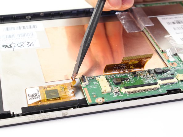
    • Disconnect the LCD screen ribbon by lifting up the black panel with the flat end of a spudger and sliding the gold strip out.

    • When reconnecting the LCD connector ribbon, make sure that it's pushed in all the way. If it isn't, there will be horizontal lines when you power the tablet on.

  14. この手順は未翻訳です。 翻訳を手伝う。

    : 手順 14、 2の画像 1 : 手順 14、 2の画像 2
    • Likewise, disconnect the square radio chip ribbon by lifting up the black panel with a spudger and sliding the gold strip out.

  15. この手順は未翻訳です。 翻訳を手伝う。

    : 手順 15、 2の画像 1 : 手順 15、 2の画像 2
    • You will be using a #00 Phillips Head screwdriver to free the motherboard.

    • Remove the six 1.75mm x 3mm Phillips Head screws holding the motherboard to the screen.

  16. この手順は未翻訳です。 翻訳を手伝う。

    : 手順 16、 2の画像 1 : 手順 16、 2の画像 2
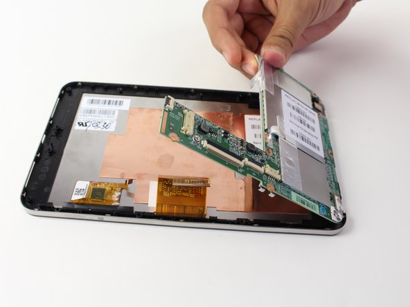
    • Using your hand, lift up the silver tape from the copper plate.

    • Lift the motherboard out of the device.

    • You may need to wiggle and work the motherboard to get it released from the device

ゴール

4 の人々がこのガイドを完成させました。

作成者

4人の作成者と共同で作成されました。

Davis Muxlow

メンバー登録日: 04/14/14

242 ポイント

1ガイドが承認済み

チーム

Cal Poly, Team 13-30, Maness Spring 2014 Cal Poly, Team 13-30, Maness Spring 2014人のメンバー

CPSU-MANESS-S14S13G30

3 メンバー

8のガイドは作成済み

コメント 1 件

We have 7 inch Hp tablet please replace motherboard sir

Sushmitha - 返信

コメントを追加

統計データ:

過去 24時間: 0

過去 7 日: 1

過去 30 日: 5

今までの合計 3,760