Turn off the computer, and unplug it from all external power sources.
Lay the computer face-down on a flat surface. Orient the computer to match the image.
Locate the battery release switch, as indicated in the image by the red rectangle. Slide the switch from right to left, and remove the battery.
Remove the two 5mm Phillips screws on the right side of the RAM cover.
Lift the right side of the RAM cover, and remove it.
Slide the hard drive to the right until the edge of the hard drive is flush with the computer frame.
Lift the hard drive out of the hard drive bay, left side first.
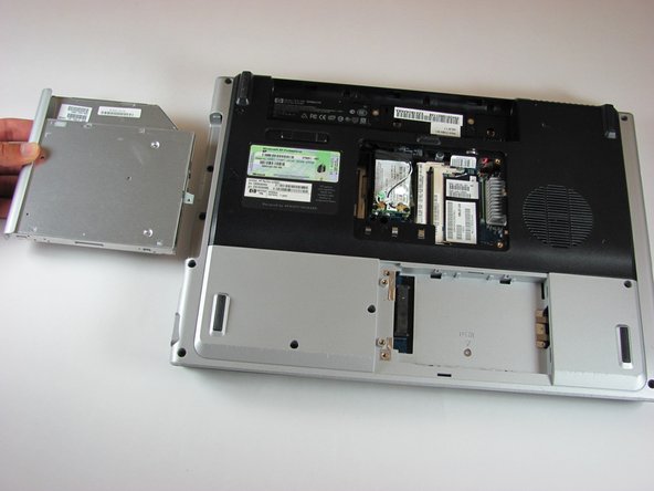
Locate the optical drive. The optical drive is located on the left side of the RAM bay.
Press the exposed edge of the optical drive gently with the spudger until the drive releases from the computer frame.
Pull the optical drive completely out of the computer frame.
Remove the two 11.0mm screws at the corners on either side of the battery compartment.
Remove the three 6.0mm screws.
Remove the two 5.0mm screws.
Remove the 6.0mm screw in the middle of the battery compartment.
Turn the computer over and open the screen. This provides access to the screen hinges.
The keyboard switch cover is attached to the computer with a series of snaps. With a flathead screwdriver, pry up the switch cover until it pops free.
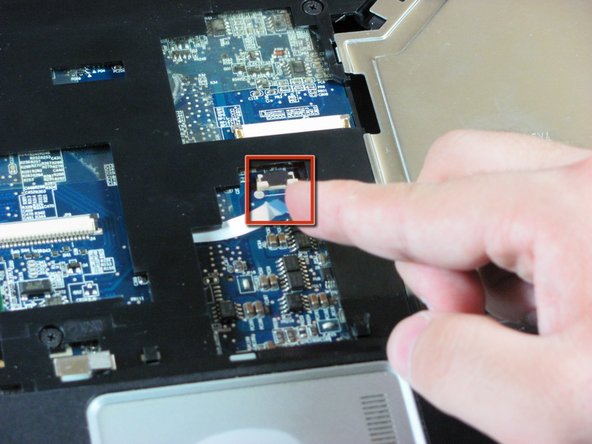
Carefully lift the trackpad-side edge of the keyboard to reveal the LED and keyboard cable connectors.
Detach the cable connectors from the computer by gripping each cable connector close to the computer contact point and pulling up gently.
This step is for replacing the keyboard only. If you are not replacing the keyboard, skip this step.
Lay the keyboard face down.
Remove the four 3.00mm screws that attach the keyboard to the keyboard frame.
This step is for replacing the keyboard only. If you are not replacing the keyboard, skip this step.
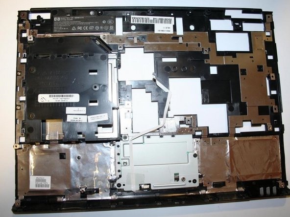
Lift the keyboard off the keyboard frame.
このガイドを埋め込む
サイズを選択し、以下のコードをコピーして、このガイドを小さなウィジェットとしてサイト/フォーラムに埋め込みます。
1つの手順
全ガイド
小サイズ - 600px
中サイズ - 800px
大サイズ - 1200px
プレビュー