メインコンテンツにスキップ

このバージョンは誤った内容を含んでいる可能性があります。最新の承認済みスナップショットに切り替えてください。

必要な工具と部品

  1. この手順は未翻訳です。 翻訳を手伝う。

    : 手順 1、 2の画像 1 : 手順 1、 2の画像 2
    • With the case closed, place the Mini 1000 top-side down on a flat surface.

    • Push both of the battery release latches toward each other.

  2. この手順は未翻訳です。 翻訳を手伝う。

    : 手順 2、 1の画像 1
    • Lift the battery out of the Mini 1000 from the edge closest to the release latches.

  3. この手順は未翻訳です。 翻訳を手伝う。

    : 手順 3、 1の画像 1
    • Remove the following two screws:

    • One 6 mm Phillips screw

    • One 4 mm Phillips screw

  4. この手順は未翻訳です。 翻訳を手伝う。

    : 手順 4、 3の画像 1 : 手順 4、 3の画像 2 : 手順 4、 3の画像 3
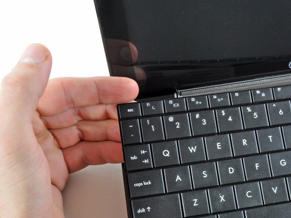
    • To facilitate the removal of the keyboard, it is recommended to push the keyboard outwards with one hand through the opening (highlighted in the third picture) located on the backside of the Mini 1000.

    • While pushing through the opening with one hand, grasp the left upper edge with the other hand and slightly pull the keyboard towards you.

    • Once an opening has been established, grasp the keyboard and slowly lift it upwards along the upper perimeter of the top edge.

  5. この手順は未翻訳です。 翻訳を手伝う。

    : 手順 5、 1の画像 1
    • Lift the keyboard out of the upper case, minding the cable that is still connecting it to the motherboard.

  6. この手順は未翻訳です。 翻訳を手伝う。

    : 手順 6、 1の画像 1
    • Use your fingernail or the flat end of a spudger to flip up the retaining flap on the keyboard cable ZIF socket.

    • Be sure you are prying up on the retaining flap, not the socket itself.

    • Pull the cable out of its socket and remove the keyboard.

  7. この手順は未翻訳です。 翻訳を手伝う。

    : 手順 7、 2の画像 1 : 手順 7、 2の画像 2
    • Use your fingernail or the flat end of a spudger to flip up the retaining flap on the SIM card ribbon cable ZIF socket.

    • Be sure you are prying up on the retaining flap, not the socket itself.

    • Pull the SIM card ribbon cable out of its socket and peel it off the top of the hard drive enclosure.

  8. この手順は未翻訳です。 翻訳を手伝う。

    : 手順 8、 1の画像 1
    • Use your fingernail or the flat end of a spudger to flip up the retaining flap on the hard drive cable ZIF socket.

    • Be sure you are prying up on the retaining flap, not the socket itself.

  9. この手順は未翻訳です。 翻訳を手伝う。

    : 手順 9、 1の画像 1
    • Remove the two 4.5 mm Phillips screws securing the hard drive to the lower case.

  10. この手順は未翻訳です。 翻訳を手伝う。

    : 手順 10、 2の画像 1 : 手順 10、 2の画像 2
    • Lift the hard drive up and out of the lower case, being careful not to damage its cable in the process.

  11. この手順は未翻訳です。 翻訳を手伝う。

    : 手順 11、 1の画像 1
    • Using the sharp tip of a spudger, pry and remove the four plastic screw covers from the underside of the HP Mini 1000.

    • There are three different variations of the covers:

    • The two bottom covers are short in height and are notched to prevent incorrect insertion

    • The upper right cover is taller in height and is notched.

    • The upper left cover is taller in height and is not notched.

  12. この手順は未翻訳です。 翻訳を手伝う。

    : 手順 12、 1の画像 1
    • Remove the four 7 mm Phillips screws that secure the upper case to the lower case.

  13. この手順は未翻訳です。 翻訳を手伝う。

    : 手順 13、 1の画像 1
    • Flip the computer over and open the display.

    • Remove the two 4.5 mm Phillips screws securing the upper case to the lower case.

  14. この手順は未翻訳です。 翻訳を手伝う。

    : 手順 14、 2の画像 1 : 手順 14、 2の画像 2
    • Wedge the flat end of a spudger in between the upper case and lower case near the bottom right corner of the display.

    • Carefully pry and rock the spudger upwards to create a small gap between the upper case and lower case.

    • Continue the previously described motion along the right edge of the upper case to release the clips securing the upper case to the lower case.

  15. この手順は未翻訳です。 翻訳を手伝う。

    : 手順 15、 2の画像 1 : 手順 15、 2の画像 2
    • Repeat the same procedure as mentioned in the previous step to release the clips along the left side of the upper case.

  16. この手順は未翻訳です。 翻訳を手伝う。

    : 手順 16、 1の画像 1
    • Grasp the upper case and carefully lift it slightly upwards, freeing it from any remaining clips.

    • The upper case is still attached via the TouchPad ribbon cable that is connected to the motherboard. Do not remove it completely just yet.

  17. この手順は未翻訳です。 翻訳を手伝う。

    : 手順 17、 1の画像 1
    • Lay the upper case on top of the upper portion of the motherboard.

    • Use your fingernail or the flat end of a spudger to flip up the retaining flap on the TouchPad cable ZIF socket.

    • Be sure you are prying up on the retaining flap, not the socket itself.

    • Pull the TouchPad ribbon cable out of its socket.

    • Remove the upper case from the HP Mini 1000.

  18. この手順は未翻訳です。 翻訳を手伝う。

    : 手順 18、 1の画像 1
    • If present, peel the sticker up off the top of the Wi-Fi board to reveal the Wi-Fi antenna connectors.

  19. この手順は未翻訳です。 翻訳を手伝う。

    : 手順 19、 3の画像 1 : 手順 19、 3の画像 2 : 手順 19、 3の画像 3
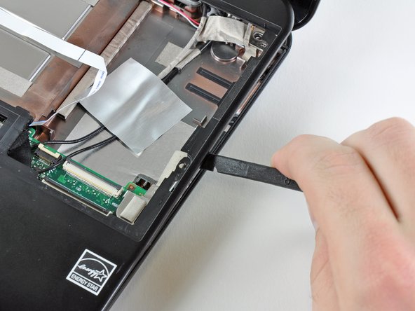
    • Pry the Wi-Fi antenna connectors (2 total) up off the Wi-Fi board.

    • During reassembly, remember to correctly connect the antenna cables to their respective terminals. The green labeled antenna is connected to the "MAIN" terminal and the white labeled antenna is connected to the "AUX" terminal.

  20. この手順は未翻訳です。 翻訳を手伝う。

    : 手順 20、 1の画像 1
    • Remove the single 3 mm Phillips screw securing Wi-Fi board to the motherboard.

  21. この手順は未翻訳です。 翻訳を手伝う。

    : 手順 21、 1の画像 1
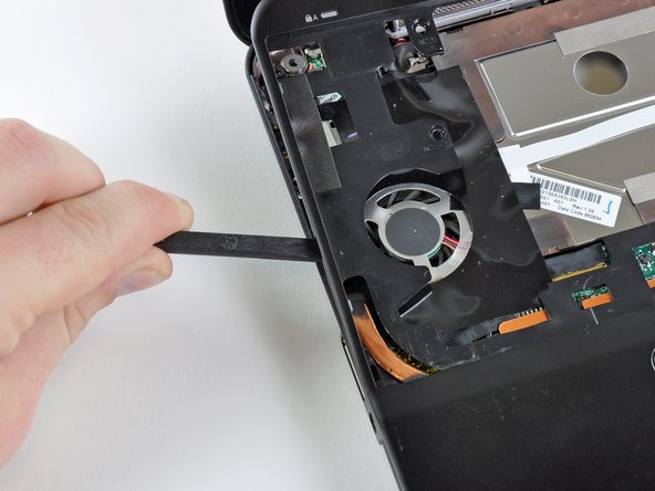
    • Upon removing the Phillips screw that secures the Wi-Fi board to the motherboard, the Wi-Fi board should pop up from its top side nearest the antenna sockets.

    • Grasp the Wi-Fi board and lift it straight away from its socket on the motherboard.

ゴール

作成者

2人の作成者と共同で作成されました。

Walter Galan

694,692 ポイント

1,203のガイドは作成済み

0 件のコメント

コメントを追加

統計データ:

過去 24時間: 0

過去 7 日: 1

過去 30 日: 2

今までの合計 2,917