メインコンテンツにスキップ

Graco Secure Coverage LED Nursery Unit Replacement

必要な工具と部品

  1. Graco Secure Coverage LED Nursery Unit Replacement, Nursery Unit Battery: 手順 1、 3の画像 1 Graco Secure Coverage LED Nursery Unit Replacement, Nursery Unit Battery: 手順 1、 3の画像 2 Graco Secure Coverage LED Nursery Unit Replacement, Nursery Unit Battery: 手順 1、 3の画像 3
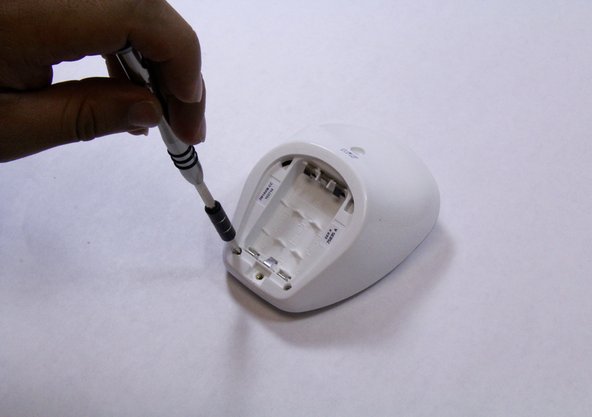
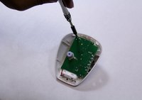
    • Remove the 9mm screw from the battery cover of the nursery unit using a Phillips #1 tip screwdriver.

  2. Graco Secure Coverage LED Nursery Unit Replacement: 手順 2、 2の画像 1 Graco Secure Coverage LED Nursery Unit Replacement: 手順 2、 2の画像 2
    • Using the plastic opening tool, pry and remove the battery cover carefully.

    • Remove the batteries using plastic opening tool.

    • Replace the batteries.

  3. Graco Secure Coverage LED Nursery Unit Replacement, LED Nursery Unit: 手順 3、 2の画像 1 Graco Secure Coverage LED Nursery Unit Replacement, LED Nursery Unit: 手順 3、 2の画像 2
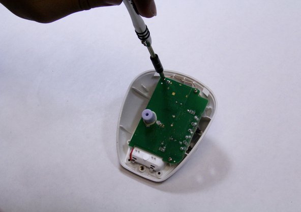
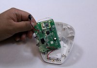
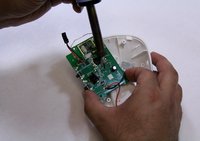
    • Remove the two 9mm Phillips #1 screws from the rare case of the device.

    • Place the screws in a secure place.

  4. Graco Secure Coverage LED Nursery Unit Replacement: 手順 4、 1の画像 1
    • Hold the bottom of the device with one hand and pull down to separate the front and rare cases.

    • While holding the device with one hand, use plastic opening tool to pry the edges of the front case away from the back case.

    • Apply constant force carefully to avoid breaking any other plastic parts from the device.

  5. Graco Secure Coverage LED Nursery Unit Replacement: 手順 5、 2の画像 1 Graco Secure Coverage LED Nursery Unit Replacement: 手順 5、 2の画像 2
    • Remove all three 7mm Phillips #1 screws from the mother board.

    • Place the screws in secure place.

  6. Graco Secure Coverage LED Nursery Unit Replacement: 手順 6、 3の画像 1 Graco Secure Coverage LED Nursery Unit Replacement: 手順 6、 3の画像 2 Graco Secure Coverage LED Nursery Unit Replacement: 手順 6、 3の画像 3
    • Flip over the motherboard to look at the LED pins that are connected to it.

    • Solder off the LED pin from the motherboard.

    • There are many pins are connect to the motherboard, so make sure that you solder off the LED pin.

    • Replace the LED.

終わりに

To reassemble your device, follow these instructions in reverse order.

作成者

2人の作成者と共同で作成されました。

Bryson Wolff

メンバー登録日: 08/31/15

237 ポイント

2のガイドは作成済み

チーム

USF Tampa, Team 6-5, Remmell Fall 2015 USF Tampa, Team 6-5, Remmell Fall 2015人のメンバー

USFT-REMMELL-F15S6G5

4 メンバー

8のガイドは作成済み

0 件のコメント

コメントを追加

統計データ:

過去 24時間: 0

過去 7 日: 2

過去 30 日: 3

今までの合計 136