-
-
SIMエジェクトツーツを、デバイス本体の左端にあるSIMカードトレイ上にある小さな穴にまっすぐ差し込みます。
-
しっかりと押し込んで、トレイを取り出します。
-
SIMカードトレイを取り出します。
-
-
-
iOpenerを準備して、デバイスのバックパネル下側端に約1分間載せます。
-
-
-
差し込んだ開口ピックを、左側コーナーに向けて下部をスライドして、接着剤を切開します。
-
ピックを差し込んだままで、左下コーナーから右下コーナーに向けて下部端をスライドして、接着剤を切開します。
-
接着剤の再装着を防ぐため、ピックを右下コーナーに残したままにします。
-
-
-
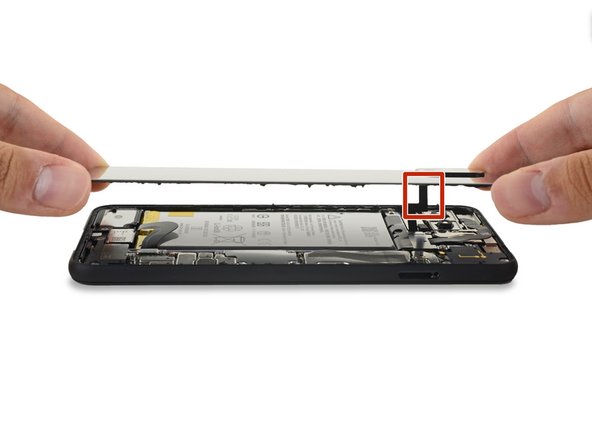
最初の2枚目の開口ピックを残したまま、3枚目の開口ピックをデバイス右端の下側に差し込みます。
-
開口ピックをデバイス上部に向けてスライドして、右側の接着剤をスライスします。
-
右上コーナーに到達したら止めて、ピックをその場に残しておきます。
-
-
-
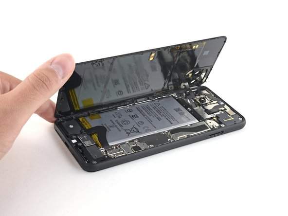
デバイス周辺の接着剤のスライスが終わったら、本を開くように、バックカバーの右端を慎重に持ち上げます。
-
パネルを完全に外さないでください。デバイスにケーブルが繋がっています。
-
-
-
付属のリボンケーブルにストレスを加えないように注意しながら、バックパネルをデバイス左端に載せれるまで開きます。
Geoff B: These are good instructions. Any technician worth his or her salt will test the device for functionality before sealing it up. That’s why it reads, “During reassembly…and test all functions before sealing it up.” Not confusing if you read and comprehend the full pin.
No instructions on how to fit new sticky gasket before assembly. Removing old adhesive was a messy business, I used IPA on a cotton bud and removed as much as possible with flat end of spudger and kitchen paper.
-
-
-
バッテリーコネクタシールドを固定しているT3トルクスネジを4本外します。
-
1.8 mmネジー1本
-
4.1 mmネジー1本
-
4.4 mm肩ツキネジー1本
-
4.0 mm肩ツキネジー1本
Anyone know the thread size of the 1.8mm screw mentioned here? Mine went missing, and I need to get a replacement. I've got a bunch of tiny screw kits, but none of them have fit!
-
-
-
-
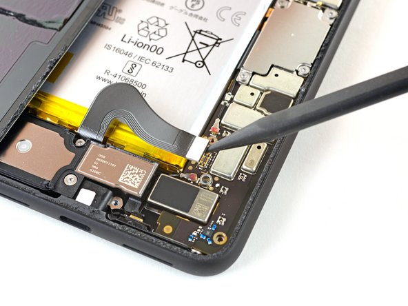
スパッジャーの先端を使用して、バッテリーコネクタをマザーボードからまっすぐ上にこじ開けてバッテリーを外します。
What are the 5 copper dots under the battery connector for.
When you reattach the connector to the motherboard this is a good time to power up and check basic functionality temporarily. Even though it had appeared it was correctly lined, my camera was not functional, in particular the switch button from the rear to the front camera, I was stuck in selfie mode. Then I was getting a message on the screen, possible hardware or software issues. Once I reattached the connecter (several times) until it was correctly inlined, the error went away and I was able to switch from the rear and front cameras.
That was a good call! Thanks!
Esther -
-
-
-
T3トルクスドライバーを使って、バックパネルのコネクタカバーを固定している4.1mmネジを2本外します。
Wouldn’t it make more sense to use the same (orange) color circles as the other 4.1mm screw?
Maybe Google did it to avoid exchange in the models where they differ
-
-
-
バックパネルを取り出します。
REASSEMBLY ADHESIVE: This is the step during reassembly that you'll want to set the back glass adhesive strip on (before you reattach ribbons). Set the adhesive strip into the body of the phone with the red tabs down (toward the body of the phone, it will simply rest inside the lip of the phone body). Press the back glass onto the adhesive strip to set the strip onto the back glass, lift the back glass back out of the body of the phone. Next reattach the ribbons, test functions, reattach connector covers, peel red adhesive cover off of the adhesive (on the back glass) then set the back glass into the phone lip. This could have been explained far better but was skipped over and the generic adhesive instructions posted in the comments are useless for this.
There are also detailed instructions at answer 742532, "How do I apply new back panel adhesive on a Pixel 4xl?" (sorry it doesn't let me link directly). But it advises adhering the adhesive to the main frame first before the glass. I do notice a slight lip on the main frame on both sides, which seems less forgiving to align with than the glass, so I would imagine doing the frame first would be easier? I haven't done this yet myself, so would be interested in opinions.
Update: it appears the discrepancy is due to a difference between the third-party adhesives and the iFixit "genuine" one. The iFixit one is not mirror symmetric and must be adhered to the glass back first, though it has cutouts that avoid protrusions and facilitate this. The third-party one (I believe) has no such cutouts and thus must go on the frame first.
However, in trying to follow Michael's instructions, I could not get the adhesive and red tabs off the blue plastic without distorting the adhesive, and had to take the clear side off first. I ended up directly placing the adhesive onto the glass back, without the frame to help align (I posted my method in the above-mentioned answer 742532). The cutouts in the blue plastic seem to have been made with this in mind.
-
-
-
ピンセットで、フロントカメラとセンサーアセンブリを外します。
Additional Sensor from Step 28 is held down with adhesive. Gently pry up on cable to remove sensor assembly.
-
-
-
スパッジャーの先端を使って、マザーボードからサイドボタン用コネクタの接続を外します。
-
2つの背面向きカメラのコネクタの接続を、マザーボードから外します。
The screw on the top left of the motherboard is out in this picture, but removal is not included in previous steps. It’s still visible in Step 30.
Thank you! Good catch. I’ve added a new step for removing that screw.
-
-
-
リボンケーブルのコネクタを引っ掛けないように注意しながら、マザーボードからゆっくりと持ち上げます。
-
マザーボードを取り出します。
-


オリジナルのパーツと交換用パーツをよく見比べてください。交換用パーツに付いていない残りのコンポーネントや接着シールなどは、インストールする前に新パーツに移植する必要があります。
このデバイスを再組み立てするには、インストラクションを逆の順番に従って作業を進めてください。
e-wasteを処理する場合は、認可済みリサイクルセンターR2を通じて廃棄してください。
修理が上手く進みませんか?ベーシックなトラブルシューティングのページを参照するか、このモデルのアンサーコミュニティに尋ねてみましょう。
オリジナルのパーツと交換用パーツをよく見比べてください。交換用パーツに付いていない残りのコンポーネントや接着シールなどは、インストールする前に新パーツに移植する必要があります。
このデバイスを再組み立てするには、インストラクションを逆の順番に従って作業を進めてください。
e-wasteを処理する場合は、認可済みリサイクルセンターR2を通じて廃棄してください。
修理が上手く進みませんか?ベーシックなトラブルシューティングのページを参照するか、このモデルのアンサーコミュニティに尋ねてみましょう。
3 の人々がこのガイドを完成させました。
以下の翻訳者の皆さんにお礼を申し上げます:
100%

Midori Doiさんは世界中で修理する私たちを助けてくれています! あなたも貢献してみませんか?
翻訳を始める ›


コメント 1 件
Hi Sir,
I folllowed this instruction to replace my rear camera but when I assembled again, everything works fine but front camera cannot be detected and faceid not working. It show black screen when I flipped from rear to front camera, faceid show “ face enrollment was not completed?
I am carefull person. I flashed many stock firmwares again but it didn't work. Hope to get your help.
Many thanks.
Tan Vo Huu - 返信