必要な工具と部品
-
-
Remove the faceplate by carefully prying around the edge using a plastic opening tool. Loosen the clips on the edge, then pull the faceplate off.
-
Use the tweezers to lift the faceplate from the rest of the device.
-
-
-
Using a #00 Phillips head screwdriver, remove the following screws:
-
One 4.6 mm screw
-
Three 8.2 mm screws
-
Two 6.1 mm screws
Any more detailed specs on these screws available? Need to but a replacement set, where to buy? How can I find them, size of the head, and the depth etc! Thanks!!
Please note the 4.6 mm screw goes aver the battery door not next to the screen.
+1 on the 4.6mm screw being bottom left not top left
´+1, broke my shell because of this.
There is absolutely no need to remove those 2 screws under the lens… -.-
-
-
-
-
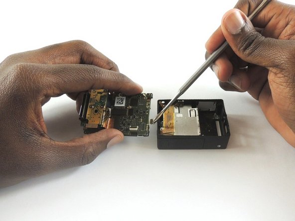
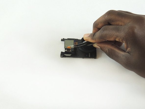
Using tweezers, remove the ribbon strip by pulling on it. This will remove the connection.
-
Push down on the three wires with the metal spudger and the clip will disconnect from the motherboard.
Removing the tiny gold ribbon strip and the wires from the right hand side as shown in the image is an unnecessary step to change out the lens. In fact it is recommendable to NOT remove these, especially the gold ribbon strip that is shown in the red box. It is very difficult to get this ZIF cable back in place once it has been removed. Simply open the camera carefully so as not to pull on this cable and the wires and proceed with the other steps.
Greg Ryder - 返信
I agree that the 2 cables shown above do NOT need to be removed in order to replace the image sensor. Just keep the internal assembly (circuit boards) close to the black housing and at a 90 degree angle. Don’t put any strain on the cables though! You can still access the 4 screws holding the sensor board in place as well as pull up the connector attaching the sensor to the mainboard. You’ll save a lot of time (and headache) by leaving those cables attached.
If you are having trouble connecting the Ribbon cable in particular, use tape to hold buttons in place, remove battery housing & connect the cables up to the battery housing. Then carefully reinsert the battery housing, lay the motherboard down on the casing slightly overhanging the socket end to get to the screw holes.
those ribbon-ports have a lever to release and secure ribbon. DO NOT PULL directly nor insert ribbons without pulling levers up. once they are on right place, push levers down again (one for each ribbon)
I failed on reinserting the ribbon cable here. The “ZIF” port under the LCD was seemingly glued shut, and I ended up damaging the cable trying to reinsert it. I recommend trying one of the approaches above, including leaving these cables connected or removing the battery module from the case to make this step easier.
-
-
-
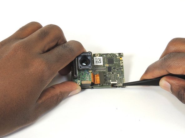
Open the clip that is located on the motherboard
-
Use a pair of tweezers to pull the ribbon from the clip
-


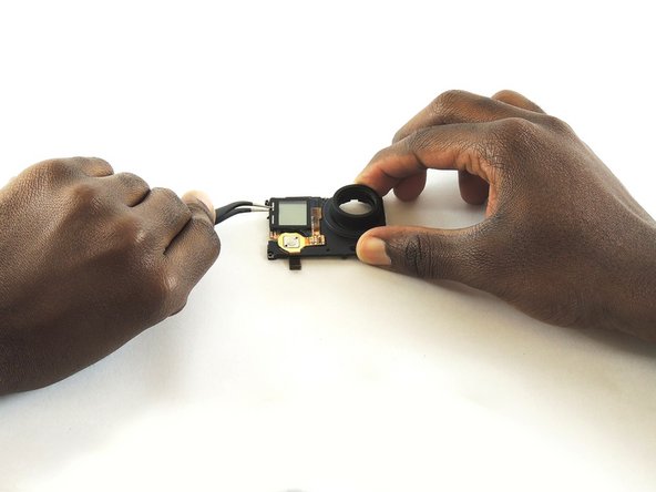


To reassemble your device, follow these instructions in reverse order.
To reassemble your device, follow these instructions in reverse order.
5 の人々がこのガイドを完成させました。
チーム

USF Tampa, Team S2-G1, Sullivan Spring 2017 USF Tampa, Team S2-G1, Sullivan Spring 2017人のメンバー
USFT-SULLIVAN-S17S2G1
4 メンバー
12のガイドは作成済み
2 件のコメント
You got the screw locations on the front wrong. Bottom left is the shortest screw, where the battery compartment is. If you try putting one of the longer screws through their it'll bust into the battery compartment. Ask me how I know. And that's the one reason why I came to this, the one thing I couldn't remember.