メインコンテンツにスキップ

このバージョンは誤った内容を含んでいる可能性があります。最新の承認済みスナップショットに切り替えてください。

必要な工具と部品

  1. この手順は未翻訳です。 翻訳を手伝う。

    : 手順 1、 3の画像 1 : 手順 1、 3の画像 2 : 手順 1、 3の画像 3
    • Remove the faceplate by carefully prying around the edge using a plastic opening tool. Loosen the clips on the edge, then pull the faceplate off.

    • Use the tweezers to lift the faceplate from the rest of the device.

    • The power button on the front of the GoPro may pop off. Ensure to align it properly during reassembly.

  2. この手順は未翻訳です。 翻訳を手伝う。

    : 手順 2、 2の画像 1 : 手順 2、 2の画像 2
    • Using a #00 Phillips head screwdriver, remove the following screws:

    • One 4.6 mm screw

    • Three 8.2 mm screws

    • Two 6.1 mm screws

  3. この手順は未翻訳です。 翻訳を手伝う。

    : 手順 3、 2の画像 1 : 手順 3、 2の画像 2
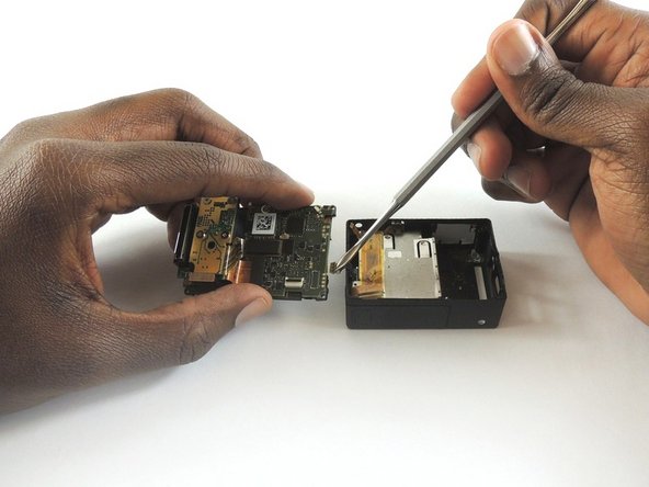
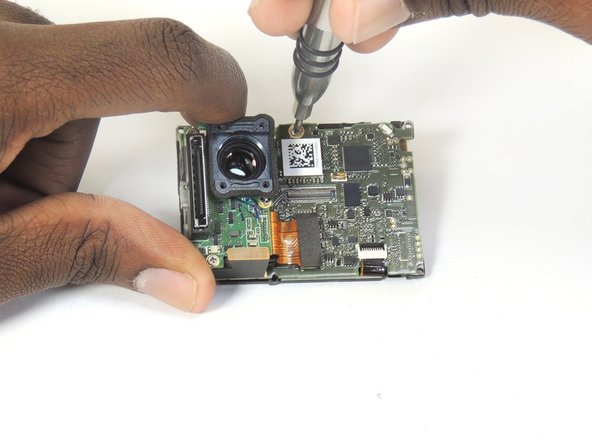
    • Insert a metal spudger between the back plastic housing and the camera board assembly. Working around the edge to be careful of the inner components, carefully remove the camera.

  4. この手順は未翻訳です。 翻訳を手伝う。

    : 手順 4、 3の画像 1 : 手順 4、 3の画像 2 : 手順 4、 3の画像 3
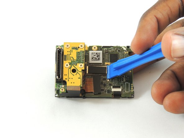
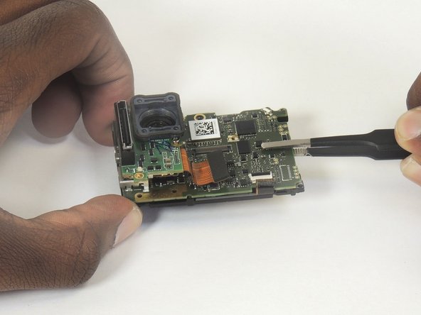
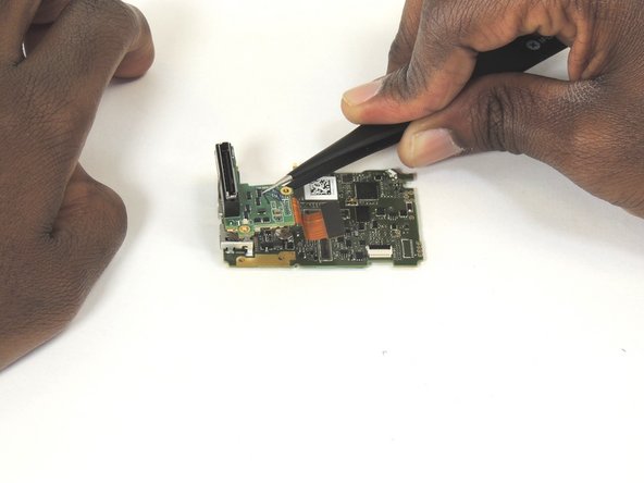
    • Using tweezers, remove the ribbon strip by pulling on it. This will remove the connection.

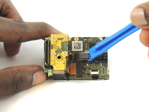
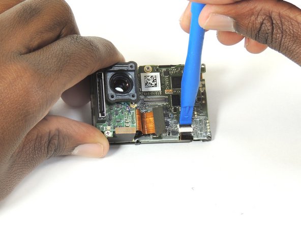
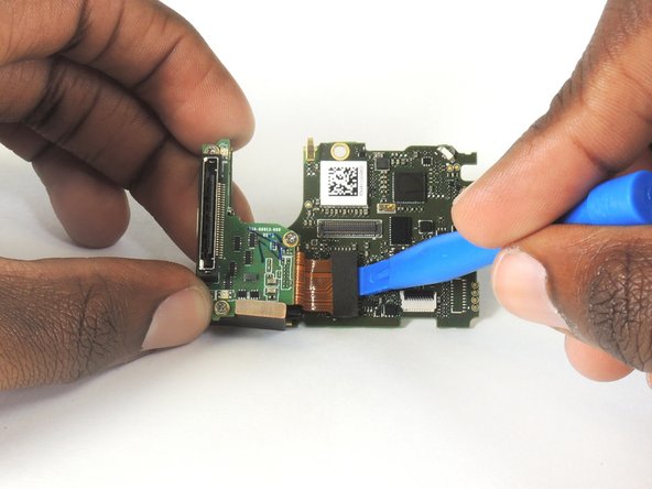
    • Push down on the three wires with the metal spudger and the clip will disconnect from the motherboard.

    • The clip must be pulled up and away from the motherboard. Attempting to slide it out will damage the clip.

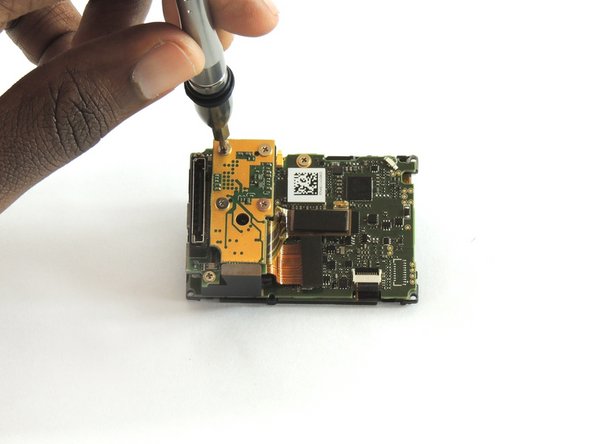
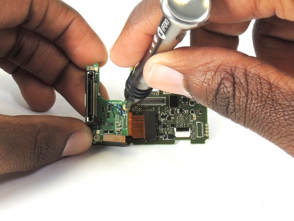
    • During reassembly, remove the black tape on the ribbon cable, turn the camera upside down so you can see the port, and reinsert the cable with tweezers. It's a lot easier!

  5. この手順は未翻訳です。 翻訳を手伝う。

    : 手順 5、 3の画像 1 : 手順 5、 3の画像 2 : 手順 5、 3の画像 3
    • Using a plastic opening tool, separate the camera sensor's connector from the motherboard.

  6. この手順は未翻訳です。 翻訳を手伝う。

    : 手順 6、 3の画像 1 : 手順 6、 3の画像 2 : 手順 6、 3の画像 3
    • Using a #00 Phillips head screwdriver, remove the four 3.0mm screws holding the camera sensor.

  7. この手順は未翻訳です。 翻訳を手伝う。

    : 手順 7、 3の画像 1 : 手順 7、 3の画像 2 : 手順 7、 3の画像 3
    • Using #00 phillips head screwdriver, remove the 3.0mm screw.

    • Using the plastic opening tool, unclip the LCD ribbon from the motherboard.

  8. この手順は未翻訳です。 翻訳を手伝う。

    : 手順 8、 2の画像 1 : 手順 8、 2の画像 2
    • Using tweezers, lift the motherboard from the midframe housing

    • It may feel like the board is still attached with a screw or two. Gentle, but firm wiggling will free the board.

  9. この手順は未翻訳です。 翻訳を手伝う。

    : 手順 9、 3の画像 1 : 手順 9、 3の画像 2 : 手順 9、 3の画像 3
    • Using #00 phillips head screwdriver, remove the three 4.0mm screws.

    • Using plastic opening tool, unclip Expansion Port chip from motherboard

    • A metal piece of the frame sits underneath the bottom screw, which will detach upon removing the screw.

  10. この手順は未翻訳です。 翻訳を手伝う。

    : 手順 10、 2の画像 1 : 手順 10、 2の画像 2
    • Lift the expansion port chip from the motherboard.

    • It is now possible to replace the expansion port and/or motherboard.

ゴール

9 の人々がこのガイドを完成させました。

作成者

6人の作成者と共同で作成されました。

Jeffrey Goethe

メンバー登録日: 02/20/17

665 ポイント

3のガイドは作成済み

チーム

USF Tampa, Team S2-G1, Sullivan Spring 2017 USF Tampa, Team S2-G1, Sullivan Spring 2017人のメンバー

USFT-SULLIVAN-S17S2G1

4 メンバー

12のガイドは作成済み

コメント 1 件

step 2 is wrong, short screw belongs on the battery door edge... destroyed my new housing... :(

Menno Middelkoop - 返信

コメントを追加

統計データ:

過去 24時間: 2

過去 7 日: 8

過去 30 日: 37

今までの合計 5,835