メインコンテンツにスキップ

このバージョンは誤った内容を含んでいる可能性があります。最新の承認済みスナップショットに切り替えてください。

必要な工具と部品

  1. この手順は未翻訳です。 翻訳を手伝う。

    : 手順 1、 3の画像 1 : 手順 1、 3の画像 2 : 手順 1、 3の画像 3
    • Use the Phillips #00 screwdriver to remove the 7 screws on the sides of the camera:

    • Four 3.95mm Phillips screws located on the bottom of the camera

    • Two 3.95mm Phillips screws located on the right side of the camera

    • One 3.95mm Phillips screw located on the left side of the camera

  2. この手順は未翻訳です。 翻訳を手伝う。

    : 手順 2、 1の画像 1
    • Slide open the battery compartment cover with your thumb.

  3. この手順は未翻訳です。 翻訳を手伝う。

    : 手順 3、 3の画像 1 : 手順 3、 3の画像 2 : 手順 3、 3の画像 3
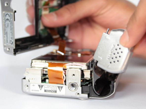
    • Wedge the edge of the spudger between the front and back case, near the corner of the flash.

    • Carefully run the spudger along the right edge of the camera, creating an opening.

    • Insert the spudger into the left side of the camera, above the screwhole. Then carefully run it along this edge.

  4. この手順は未翻訳です。 翻訳を手伝う。

    : 手順 4、 2の画像 1 : 手順 4、 2の画像 2
    • Watch out for the orange ribbon that is still attached to the back cover when you lift it up. It is very delicate and might rip.

    • Slowly lift the back cover straight up, lightly jiggling it if necessary.

    • Remove the battery compartment cover.

  5. この手順は未翻訳です。 翻訳を手伝う。

    : 手順 5、 1の画像 1
    • Gently insert the spudger under the clip holding the orange ribbon. The clip should lift up and the ribbon will slide out.

    • This step will free the back cover from the rest of the camera.

  6. この手順は未翻訳です。 翻訳を手伝う。

    : 手順 6、 1の画像 1
    • Pull gently when removing the speaker so you don't rip the wire attached to it.

    • Use the tweezers to grab the speaker (located on left side of the camera) and pull straight up.

    • The speaker will still be connected to the motherboard, but it will not be attached to the front case.

  7. この手順は未翻訳です。 翻訳を手伝う。

    : 手順 7、 1の画像 1
    • Use the tweezers to pull gently on the small orange ribbon, located in upper left hand corner near the flash, to remove the square insert.

  8. この手順は未翻訳です。 翻訳を手伝う。

    : 手順 8、 1の画像 1
    • Use your fingers to slowly pull the flash straight up.

    • The step may take a little jiggling.

  9. この手順は未翻訳です。 翻訳を手伝う。

    : 手順 9、 2の画像 1 : 手順 9、 2の画像 2
    • Do not fully separate the motherboard unit from the front cover. There is still a ribbon attached and it will rip.

    • Slightly separate the front cover from the motherboard unit (which consists of the motherboard, speaker, screen, and battery compartment).

    • Rotate the bottom portion of the motherboard unit (the screen and battery compartment) over the lens unit.

  10. この手順は未翻訳です。 翻訳を手伝う。

    : 手順 10、 1の画像 1
    • Use your fingers to remove the tripod mount.

  11. この手順は未翻訳です。 翻訳を手伝う。

    : 手順 11、 3の画像 1 : 手順 11、 3の画像 2 : 手順 11、 3の画像 3
    • Be gentle when undoing the ribbon clips. They break easily.

    • Gently stick the spudger under the ribbon clips and lift them up.

    • Use the tweezers to pull both ribbons out of the ribbon clips.

    • The motherboard unit should now be free from the rest of the camera.

ゴール

作成者

7人の作成者と共同で作成されました。

Sarthak Patel

メンバー登録日: 04/03/12

10 ポイント

2のガイドは作成済み

チーム

Cal Poly, Team 14-8, Forte Spring 2012 Cal Poly, Team 14-8, Forte Spring 2012人のメンバー

CPSU-FORTE-S12S14G8

5 メンバー

17のガイドは作成済み

0 件のコメント

コメントを追加

統計データ:

過去 24時間: 1

過去 7 日: 8

過去 30 日: 20

今までの合計 891