メインコンテンツにスキップ

Front Fan Assembly (Early 2008)

必要な工具と部品

  1. Front Fan Assembly (Early 2008), Hard drives and hard drive carriers (Early 2008): 手順 1、 1の画像 1
    • The hard drives must meet the following specifications:

    • Type: Serial Attached SCSI (SAS) or Serial ATA (SATA) 3 Gb/s

    • Width: 3.9 inches (102 mm)

    • Depth: 5.7 inches (147 mm)

    • Height: 1.0 inch

  2. Front Fan Assembly (Early 2008): 手順 2、 1の画像 1
    • Important: To install SAS drives in a Mac Pro (Early 2008) computer, you must also install the optional Mac Pro RAID Card.

  3. Front Fan Assembly (Early 2008): 手順 3、 1の画像 1
    • Before you begin, open the computer, and lay it on its side with the access side facing up.

    • Important: Make sure the latch on the back panel is in the up position. When the latch is down, the hard drives and carriers are locked in place and you will not be able to remove them.

  4. Front Fan Assembly (Early 2008): 手順 4、 1の画像 1
    • Make sure the latch on the back panel is up, so that the drives and carriers are unlocked.

    • Pull the hard drive out of the drive bay.

  5. Front Fan Assembly (Early 2008): 手順 5、 1の画像 1
    • If you are replacing the hard drive with a new drive, remove the four screws that mount the 3. drive to the carrier and mount the new drive in the carrier.

    • Important: Hold the drive by its sides. Be careful not to touch the printed circuit board on the bottom of the drive.

    • Replacement Note: Slide the carrier and drive over the guides and into the drive bay, until you feel the drive snap into place.

  6. Front Fan Assembly (Early 2008), Graphic Card for Mac Pro (2006-2008): 手順 6、 2の画像 1 Front Fan Assembly (Early 2008), Graphic Card for Mac Pro (2006-2008): 手順 6、 2の画像 2
    • This procedure explains how to remove a standard card and a card that includes a booster cable. Before you can remove either type of card, however, you must first loosen the two captive screws that secure the PCI bracket to the enclosure and remove the bracket.

  7. Front Fan Assembly (Early 2008): 手順 7、 1の画像 1
    • Handle the card only by the edges.Do not touch its connectors or any of the components.Lift the card straight out from the connector to remove it, and insert it straight into the connector to install it.Do not rock the card from side to side and don’t force the card into the slot.Once the replacement card is installed, pull on it gently to check.

    • 1) Release the small locking clip at the front of the card’s logic board connector by pushing the clip up toward the media shelf.

    • 2) Holding the card by the top corners, pull up the card and remove it from its expansion slot.

  8. Front Fan Assembly (Early 2008), Card with Booster Cable: 手順 8、 2の画像 1 Front Fan Assembly (Early 2008), Card with Booster Cable: 手順 8、 2の画像 2
    • Some graphics cards require either one or two booster cables connecting the card to the auxillary power connectors on the logic board.

    • The graphics card NVIDIA GeForce 8800 GT requires one booster cable; the graphics card NVIDIA Quadro FX 5600 requires two booster cables.

    • Disconnect the booster cable(s) from the logic board.

    • Release the small locking clip at the front of the card’s logic board connector by pushing the clip up toward the media shelf.

    • Holding the card by the top corners, gently pull up the card and remove it from its expansion slot.

    • If you are replacing a booster cable with a new one, disconnect the cable from the card.

  9. Front Fan Assembly (Early 2008): 手順 9、 1の画像 1
    • Replacement Note for Card Using One Booster Cable: Be sure to connect the card’s booster cable to the correct auxillary power connector on the logic board. Connect the booster cable for a card in PCI slot 1 to the lower connector. Connect the booster cable for a card in PCI slot 2 to the upper connector.

    • Replacement Note for Card Using Two Booster Cables: Connect both cables to the two auxillary power connectors.

  10. Front Fan Assembly (Early 2008), PCI Express Cards (Early 2008): 手順 10、 1の画像 1
    • The procedure to remove the graphic cards is the same for PCI Express Cards for exception of minor card differences.

    • Important: Combined maximum power consumption for all four PCI Express slots must not exceed 300 W.

  11. Front Fan Assembly (Early 2008), Processor Heatsink Cover (Early 2008): 手順 11、 2の画像 1 Front Fan Assembly (Early 2008), Processor Heatsink Cover (Early 2008): 手順 11、 2の画像 2
    • Remember to check that all the PCI Express cards have been removed and properly stowed.

    • Note: The heatsink cover is held in place by a number of tabs and magnets on the underside of the cover. You must release the tabs before you can remove the cover from the enclosure.

    • Place the fingers of one hand under the lip of the heatsink cover nearest the logic board. Lift the lip slightly toward the media shelf to release the tabs and magnets under the top face of the cover.

    • With your fingers still under the cover’s bottom lip, lift the cover straight up to release the remaining tabs and magnets under the front face of the cover

    • Remove the cover from the enclosure.

  12. Front Fan Assembly (Early 2008): 手順 12、 1の画像 1
    • Replacement Note: When reinstalling the processor heatsink cover, make sure the tabs on the underside of the cover align with the slots directly below them. (The slots are on the front fan and memory cage on either side of the heatsink cover.)

  13. Front Fan Assembly (Early 2008), Front Fan Assembly (Early 2008): 手順 13、 2の画像 1 Front Fan Assembly (Early 2008), Front Fan Assembly (Early 2008): 手順 13、 2の画像 2
    • Remember: Before removing the Front Fan Assembly ensure that the first two bays of the hard drives are removed, All PCI express cards removed, and placed in a safe location.

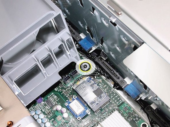
    • Using a long-handled, magnetized #1 Phillips screwdriver, remove the screw at the top rear of the front fan assembly that mounts the assembly to the logic board.

  14. Front Fan Assembly (Early 2008): 手順 14、 1の画像 1
    • Remove the second Phillips screw at the bottom front of the assembly.

  15. Front Fan Assembly (Early 2008): 手順 15、 1の画像 1
    • Place one hand on each end of the fan, lift straight up, and remove the fan from the enclosure.

  16. Front Fan Assembly (Early 2008): 手順 16、 3の画像 1 Front Fan Assembly (Early 2008): 手順 16、 3の画像 2 Front Fan Assembly (Early 2008): 手順 16、 3の画像 3
    • Replacement Note: Before re-installing the front fan assembly in the enclosure, make sure that the fan cables are routed correctly in the fan channel.

    • Replacement Note: Make sure all AirPort and Bluetooth antenna wires are out of the way before lowering the fan assembly onto the logic board.

    • Replacement Note: When lowering the front fan into the enclosure, slide the guide on the base of the fan assembly into the channel on the speaker assembly.

  17. Front Fan Assembly (Early 2008): 手順 17、 1の画像 1
    • Replacement Note: Also make sure the latch on the inside top left edge of the fan assembly engages with the slot on the inside lip of the enclosure

終わりに

To reassemble your device, follow these instructions in reverse order.

27 の人々がこのガイドを完成させました。

作成者

3人の作成者と共同で作成されました。

Joshua Byrne

メンバー登録日: 05/03/13

7,695 ポイント

10のガイドは作成済み

コメント 1 件

What types of screws are those 2 Philips screws that hold the front fan assembly in place; Steps 13 and 14. I bought a used Mac Pro and it was missing both of these screws :(

Timothéo - 返信

コメントを追加

統計データ:

過去 24時間: 3

過去 7 日: 22

過去 30 日: 127

今までの合計 33,653