この修理ガイドは変更されています。最新の未承認バージョンに切り替えます。
はじめに
Use this guide to replace just the RF Cable on your Fairphone.
必要な工具と部品
-
-
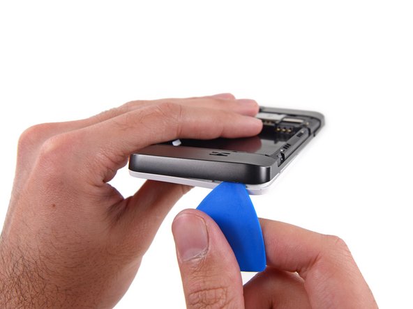
With the indentation as leverage, use your fingernail to pry the bottom portion of the back cover from the phone.
-
-
-
Use a fingernail in this indentation to push the battery toward the top of the phone
-
Pull the battery out away from the phone.
-
-
-
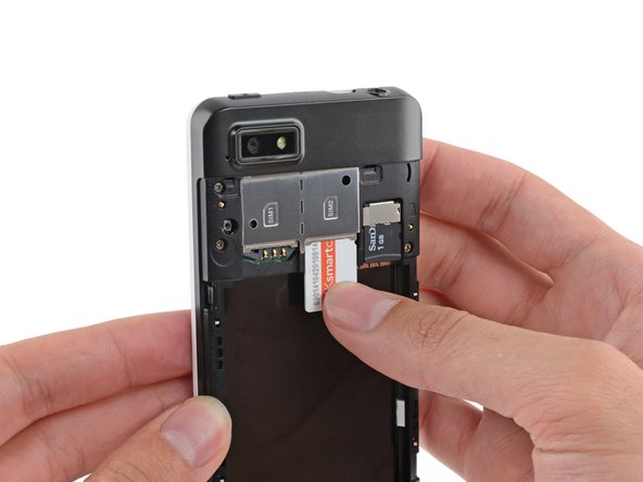
Use your finger to slide the SIM card straight down out of its tray.
-
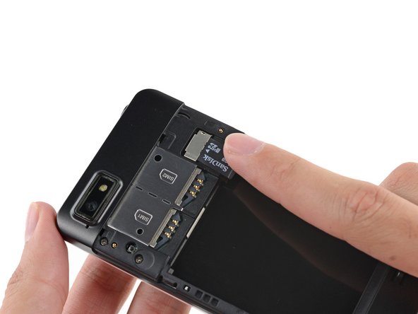
Remove the SIM card from your Fairphone.
-
-
-
Remove the five 3.9 mm Phillips #000 screws securing the midframe to the display assembly.
-
-
-
-
Use tweezers to remove the volume rocker and power buttons from the display assembly.
-
-
-
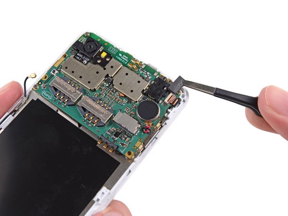
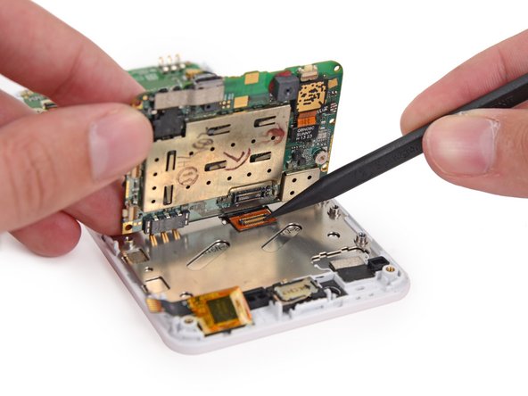
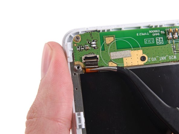
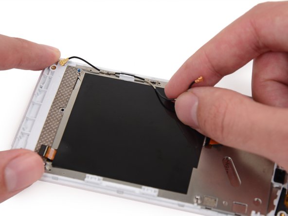
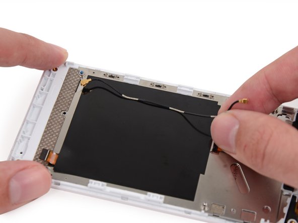
Use the flat end of a spudger to disconnect the antenna cable connector.
-
-
-
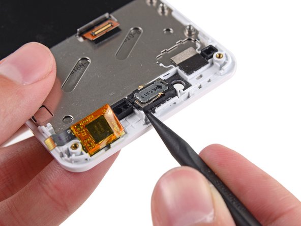
Use the tip of a spudger to gently pry the speaker up from the display assembly.
-
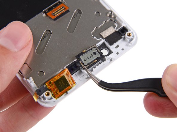
Remove the speaker.
-


To reassemble your device, follow these instructions in reverse order.
To reassemble your device, follow these instructions in reverse order.
