メインコンテンツにスキップ

Dynex DX‑PDVD9 Optical Drive Replacement

必要な工具と部品

  1. Dynex DX‑PDVD9 Optical Drive Replacement, Optical Drive: 手順 1、 1の画像 1
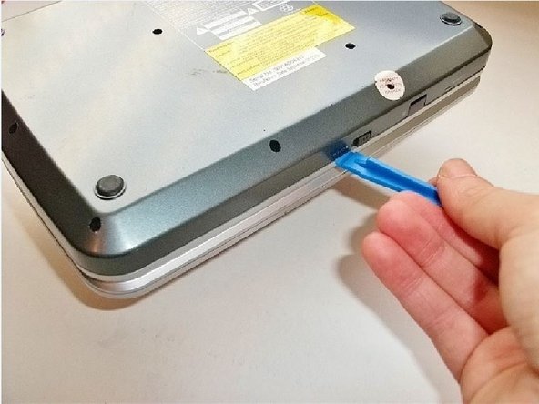
    • Before removing the screen, be sure to turn off and unplug your device.

    • Flip your device over, so the bottom is facing up.

  2. Dynex DX‑PDVD9 Optical Drive Replacement: 手順 2、 1の画像 1
    • Remove the back cover held by thirteen 3.175 mm head, 9.525 mm length pan-head Phillips screws.

    • One of the screws is covered by a seal. Breaking this seal will void your warranty.

  3. Dynex DX‑PDVD9 Optical Drive Replacement: 手順 3、 3の画像 1 Dynex DX‑PDVD9 Optical Drive Replacement: 手順 3、 3の画像 2 Dynex DX‑PDVD9 Optical Drive Replacement: 手順 3、 3の画像 3
    • Use a plastic opening tool to pop open the back case.

    • Do not separate the back cover completely, wires are still connected to both sides.

  4. Dynex DX‑PDVD9 Optical Drive Replacement: 手順 4、 2の画像 1 Dynex DX‑PDVD9 Optical Drive Replacement: 手順 4、 2の画像 2
    • Hold the back cover upright and remove the black tape connecting the wire group to the cover.

    • Remove the bottom two pieces of tape connecting wires to the CD tray.

  5. Dynex DX‑PDVD9 Optical Drive Replacement: 手順 5、 2の画像 1 Dynex DX‑PDVD9 Optical Drive Replacement: 手順 5、 2の画像 2
    • Locate the small circuit board on the underside of the buttons.

    • Remove the circuit board for the buttons, held by six 3.175 mm head, 4.762 mm length flat-head Phillips screws.

  6. Dynex DX‑PDVD9 Optical Drive Replacement: 手順 6、 3の画像 1 Dynex DX‑PDVD9 Optical Drive Replacement: 手順 6、 3の画像 2 Dynex DX‑PDVD9 Optical Drive Replacement: 手順 6、 3の画像 3
    • Remove the three wire connections that are located on the main (largest) circuit board.

    • The connection can be gently removed with a plastic opening tool or with your fingers by pinching the ends and pulling.

  7. Dynex DX‑PDVD9 Optical Drive Replacement: 手順 7、 2の画像 1 Dynex DX‑PDVD9 Optical Drive Replacement: 手順 7、 2の画像 2
    • Remove the optical disc drive by lifting it off the three pegs on the bottom case.

  8. Dynex DX‑PDVD9 Optical Drive Replacement: 手順 8、 3の画像 1 Dynex DX‑PDVD9 Optical Drive Replacement: 手順 8、 3の画像 2 Dynex DX‑PDVD9 Optical Drive Replacement: 手順 8、 3の画像 3
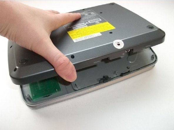
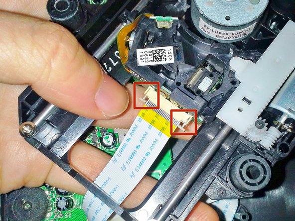
    • Now that the optical drive is removed from the case, flip it over and locate the ribbon cable.

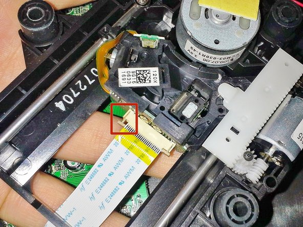
    • Gently pull out the two sides of the brown tab underneath the ribbon cable, see images for detail.

    • Once both sides of the tab are out, it should require no force to pull the ribbon cable out of the connection on the optical drive.

  9. Dynex DX‑PDVD9 Optical Drive Replacement: 手順 9、 1の画像 1
    • Now the optical drive should be removed and still connected to the circuit board which was underneath the buttons.

    • Desolder the optical drive wires from the circuit board.

    • If the wires need to be removed from the circuit board, you may need to use an adhesive solvent to fully dissolve the glue.

    • For proper soldering and desoldering techniques reference How To Solder and Desolder Connections.

    • Soldering requires the iron to be at hot temperatures and can cause burns. Wear safety glasses as needed. Be extremely careful with the wires and board in this step as they could melt, burn, or break.

終わりに

To reassemble your device, follow these instructions in reverse order.

ある他の人がこのガイドを完成しました。

作成者

1人の作成者と共同作成されました。

Roxanne Hoffman

メンバー登録日: 04/14/14

457 ポイント

2のガイドは作成済み

チーム

Cal Poly, Team 8-10, Regan Spring 2014 Cal Poly, Team 8-10, Regan Spring 2014人のメンバー

CPSU-REGAN-S14S8G10

4 メンバー

16のガイドは作成済み

0 件のコメント

コメントを追加

統計データ:

過去 24時間: 0

過去 7 日: 0

過去 30 日: 2

今までの合計 335