はじめに
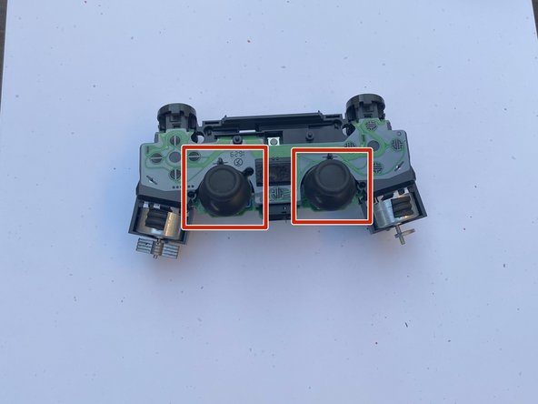
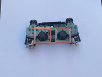
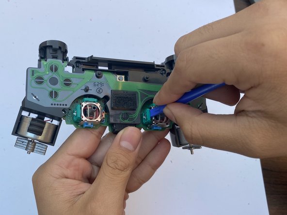
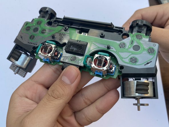
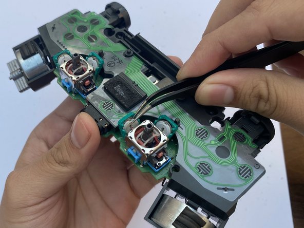
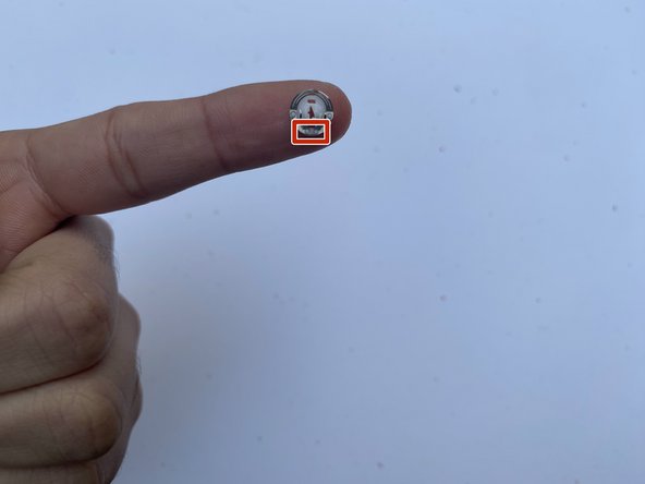
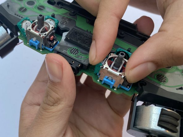
When using a joystick, it moves two brackets inside the analog stick in rotation and each of these brackets are attached to a potentiometer. The main function of a potentiometer is to measure the rotation and precise movement of the joystick. One potentiometer senses left and right movement while the other senses up and down movement. Inside the potentiometer there is a metal wiper that is attached to a white mounting bracket. When the bracket moves the wipers where it contacts the track changes which registers the joystick's position and movement. When malfunction of a joystick occurs, it is mostly due to the wear of the potentiometer. Over time, the wiper scrubbing back and forth against the resistance pad creates imperfection.
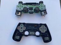
This guide will show you how to replace a damaged potentiometer from a DualShock 4 Controller (PS4 controller). The format for this guide can also be applied to a DualSense Controller (PS5 controller).
You do not need any special skills to perform this guide.
As for where to buy the potentiometer replacement, I recommend buying it from Amazon. The link I provided for the potentiometer replacement in the tools section is costly, you can find more cheap options from the Amazon website.
必要な工具と部品
-
-
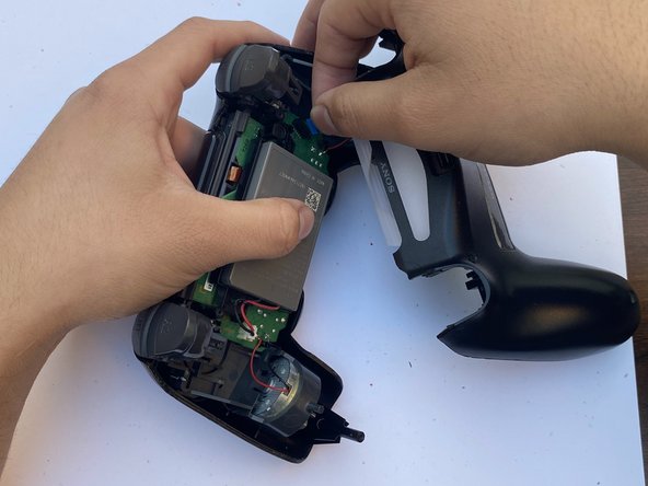
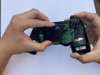
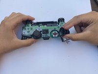
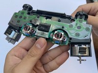
Grab you're DualShock 4 Controller that has joystick problems.
-
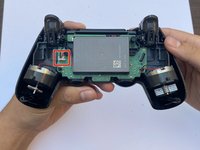
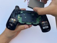
Using the Phillips #00 Screwdriver, remove the four 6.0 mm screws securing the rear cover to the controller.
-
-


To reassemble your device, follow these instructions in reverse order.
6 の人々がこのガイドを完成させました。
チーム

CSU Los Angeles, Team 3-90, Briggs Fall 2023 CSU Los Angeles, Team 3-90, Briggs Fall 2023人のメンバー
CSULA-BRIGGS-F23S3G90
1 メンバー
4のガイドは作成済み
2件のガイドコメント
How the replacement of the metal springs should it repair the issue? isn't the conductive graphite in the green part of the potentiometer the part worned out?
i would say it's both, before replacing the stick (or for inexperienced the whole pad) you could try cleaning the conductive graphite with a qtip with isopropyl alcohol, and that little curved metal part on the metal spring.
To me it didn't work but I haven't done it properly yet, I'm planning to retry it
chief -