メインコンテンツにスキップ

このバージョンは誤った内容を含んでいる可能性があります。最新の承認済みスナップショットに切り替えてください。

必要な工具と部品

  1. この手順は未翻訳です。 翻訳を手伝う。

    : 手順 1、 3の画像 1 : 手順 1、 3の画像 2 : 手順 1、 3の画像 3
    • First of all remove the battery.

    • like always : draw a map of the laptop and paste/draw where all the screws come from or use a magentic project map.

    • remove the bottom plate of the ram and HDD.

  2. この手順は未翻訳です。 翻訳を手伝う。

    : 手順 2、 2の画像 1 : 手順 2、 2の画像 2
    • now remove the hdd screw ( red circkle)

    • lift up the HDD

    • remove the ram by clicking the levars to the outside

  3. この手順は未翻訳です。 翻訳を手伝う。

    : 手順 3、 2の画像 1 : 手順 3、 2の画像 2
    • remove the screw , and use a spudger to remove the dvd bay. ( slide it out)

  4. この手順は未翻訳です。 翻訳を手伝う。

    : 手順 4、 3の画像 1 : 手順 4、 3の画像 2 : 手順 4、 3の画像 3
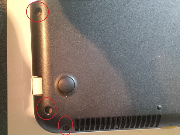
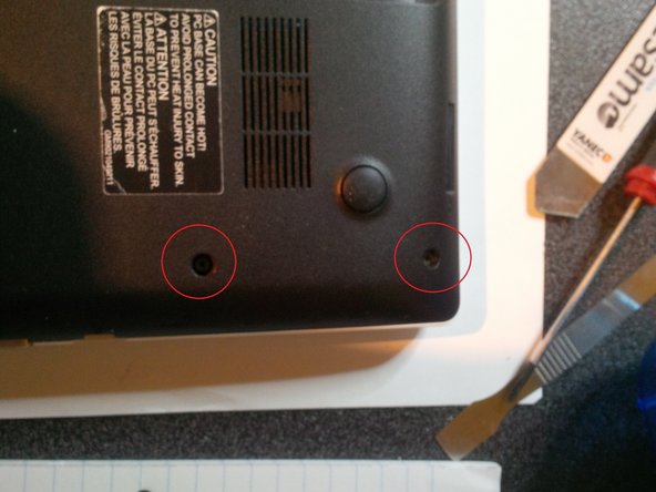
    • remove the screw of the keyboard, orange circkle

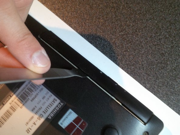
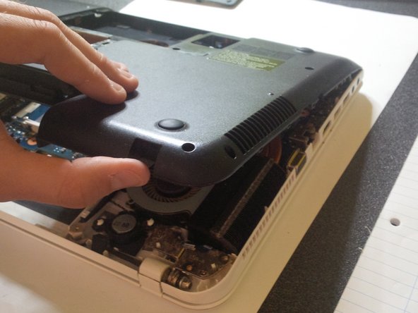
    • turn the laptop again and remove the keyboard.

    • use a isesamo to click the keyboard off the laptop. the "click levars"( 6 of them) are under number 0 , between left arrow and ctrl, alt gr , space bar, windows button and alt and ctrl(left)

    • do it very gently , you can break the keyboard or you can break some buttons off the keyboard.

    • after clicking the keyboard loose, lift the lid of the connector socket up and remove the flex cable. you can see a picture in step 6.

  5. この手順は未翻訳です。 翻訳を手伝う。

    : 手順 5、 3の画像 1 : 手順 5、 3の画像 2 : 手順 5、 3の画像 3
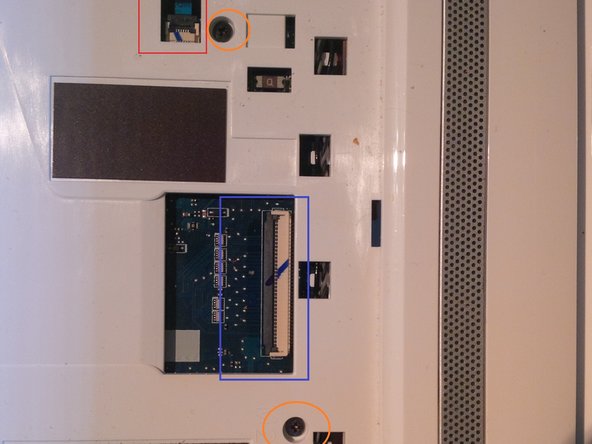
    • now you will see 2 connectors and 7 screws under the keyboard.

    • If you don't know how to remove the connectors safely see the next step.

    • remove the screws and gently remove the 2 connectors from the connectors. like always do it gently.

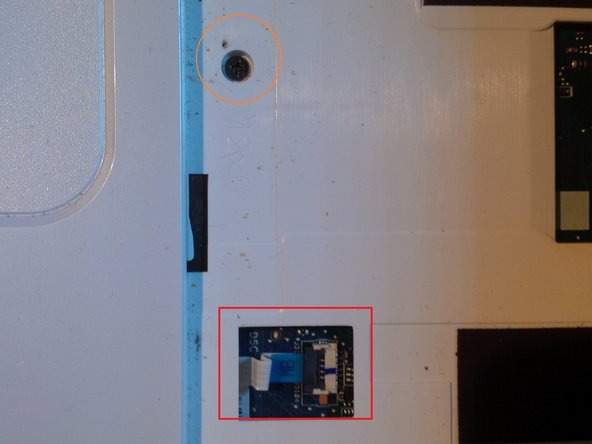
    • the orange circkles are the screws to remove the mainboard in a later step

    • the red squares are the connectors of the mouse pad and powerboard

    • the blue square is the connector from the keyboard.

  6. この手順は未翻訳です。 翻訳を手伝う。

    : 手順 6、 2の画像 1 : 手順 6、 2の画像 2
    • use a spudger or little flathead screwdriver to open the lid of the connectors.

  7. この手順は未翻訳です。 翻訳を手伝う。

    : 手順 7、 3の画像 1 : 手順 7、 3の画像 2 : 手順 7、 3の画像 3
    • again : draw a map of the laptop , so you remeber where all the screws come from. Or use a magnetic project map.

    • first screws : 3 screws in the HDD compartiment.

    • screws at the side , also see the next step for the rest of the screws.

  8. この手順は未翻訳です。 翻訳を手伝う。

    : 手順 8、 3の画像 1 : 手順 8、 3の画像 2 : 手順 8、 3の画像 3
    • remove the last screws

    • then : slide your spudger or isesamo between the bottom plate and upper plate to remove the case. you will hear clicks. be gently while sliding

  9. この手順は未翻訳です。 翻訳を手伝う。

    : 手順 9、 3の画像 1 : 手順 9、 3の画像 2 : 手順 9、 3の画像 3
    • gently remove the plate.

    • after opening you'll see the mainboard or like we call it here in Belgium : the motherboard.

  10. この手順は未翻訳です。 翻訳を手伝う。

    : 手順 10、 3の画像 1 : 手順 10、 3の画像 2 : 手順 10、 3の画像 3
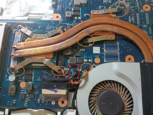
    • in this step we will show you how to remove the fan and the cooling tubes and pads for cleaning or renewing.

    • there are 8 screws and 1 connector

    • remove the screws ( 1 screw is not on the pictures, you ll find it at the bottom of the fan) but unscrew them simultaneous.

    • remove the connector ( see picture 2 ) using an IC extractor

    • remove the cooling tubes and fan.

    • clean the pads using isopropyl alcohol. you will see pieces (remnants ?) of old thermal paste.

    • if the fan itself is broken , you can replace this by removing the very tiny screws. and remove the black tape.

  11. この手順は未翻訳です。 翻訳を手伝う。

    : 手順 11、 3の画像 1 : 手順 11、 3の画像 2 : 手順 11、 3の画像 3
    • clean CPU and pads with isopropyl alcohol. But, like you know ,be carefull with this.

    • use gloves

    • you can also renew /upgrade the cpu, just use a flathead screwdriver to open the cpu socket.

  12. この手順は未翻訳です。 翻訳を手伝う。

    : 手順 12、 2の画像 1 : 手順 12、 2の画像 2
    • use gloves , cause thermal paste is very toxic.

    • one drop is enough on the CPU , and a little drop on the graphic chip.

  13. この手順は未翻訳です。 翻訳を手伝う。

    : 手順 13、 3の画像 1 : 手順 13、 3の画像 2 : 手順 13、 3の画像 3
    • removing or replacing the Mainboard :

    • first remove the LCD connector: do it very gently, there are a lot of tiny thin wires, they are very breakable. you see this in picture 2, if you have to replace the whole screen, i don't have pictures of this in this guide, but we have other guides that show you how to or you can find these here at ifixit.com

    • remove the screw you see in picture 3

  14. この手順は未翻訳です。 翻訳を手伝う。

    : 手順 14、 3の画像 1 : 手順 14、 3の画像 2 : 手順 14、 3の画像 3
    • in these 3 pictures: dc jack in picture one, + the connector, and the usb pcb. if you have to replace the dc jack, be gently with the connector.

    • second picture : wifi module. always remember the color code ( black and white)

    • third picture : mousepad and screws.

ゴール

11 の人々がこのガイドを完成させました。

作成者

4人の作成者と共同で作成されました。

Kevin D

メンバー登録日: 05/02/14

7,276 ポイント

21のガイドは作成済み

0 件のコメント

コメントを追加

統計データ:

過去 24時間: 2

過去 7 日: 6

過去 30 日: 26

今までの合計 19,972