メインコンテンツにスキップ

このバージョンは誤った内容を含んでいる可能性があります。最新の承認済みスナップショットに切り替えてください。

必要な工具と部品

  1. この手順は未翻訳です。 翻訳を手伝う。

    : 手順 1、 2の画像 1 : 手順 1、 2の画像 2
    • Turning over your phone, place two fingers on the back cover and apply pressure away from the camera to slide the back cover off.

  2. この手順は未翻訳です。 翻訳を手伝う。

    : 手順 2、 2の画像 1 : 手順 2、 2の画像 2
    • Pinch the battery pull tab located below the camera, pull it upwards, and remove the battery.

    • The pull tab may be tucked under the battery.

  3. この手順は未翻訳です。 翻訳を手伝う。

    : 手順 3、 3の画像 1 : 手順 3、 3の画像 2 : 手順 3、 3の画像 3
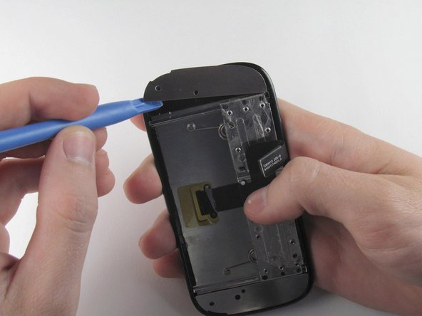
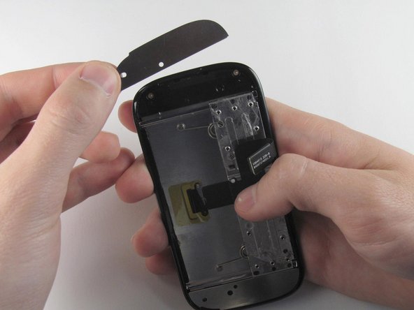
    • Wedge a plastic opening tool behind the panel covering the camera, pry it up, and remove it using your fingers.

    • The panel is held down by adhesive and may require you to wedge and pry the right side of the panel before it can be easily removed.

  4. この手順は未翻訳です。 翻訳を手伝う。

    : 手順 4、 1の画像 1
    • Remove the six 4.0 mm T4 Torx screws which line the edge of the back of the phone.

  5. この手順は未翻訳です。 翻訳を手伝う。

    : 手順 5、 3の画像 1 : 手順 5、 3の画像 2 : 手順 5、 3の画像 3
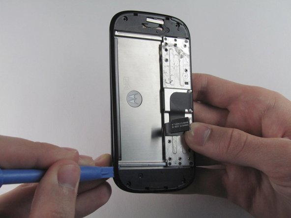
    • Turn the phone over and slide out the keyboard.

    • Wedge a plastic opening tool where the keyboard meets the back casing of the phone next to the headphone jack.

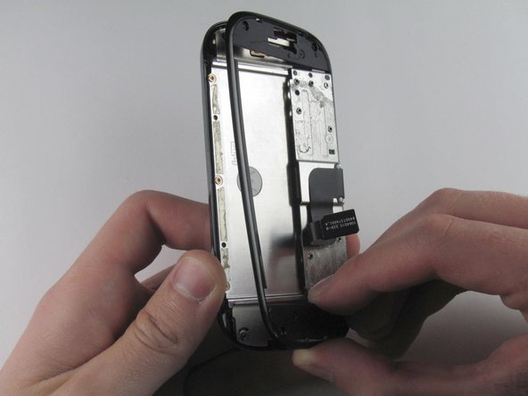
    • Carefully pry open the back casing along the keyboard's edge until at least two corners of the back casing are separated from the keyboard.

    • Do not fully separate the rear panel from the phone. A cable is connecting the two parts together.

  6. この手順は未翻訳です。 翻訳を手伝う。

    : 手順 6、 1の画像 1
    • Carefully separate the back casing from the rest of the phone.

  7. この手順は未翻訳です。 翻訳を手伝う。

    : 手順 7、 2の画像 1 : 手順 7、 2の画像 2
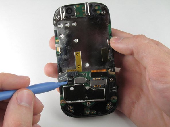
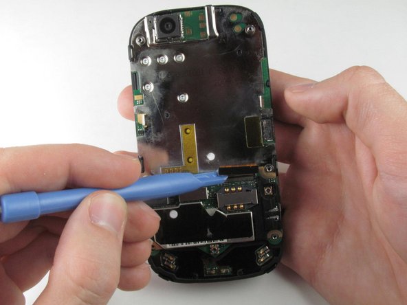
    • Gently pry ZIF connector upwards using the flat end of a spudger tool.

    • The ZIF connector is glued down. Be gentle! Ripping it off or breaking it will make your phone inoperable.

    • You may need adhesive to keep your power cable in place when reassembling your phone.

  8. この手順は未翻訳です。 翻訳を手伝う。

    : 手順 8、 3の画像 1 : 手順 8、 3の画像 2 : 手順 8、 3の画像 3
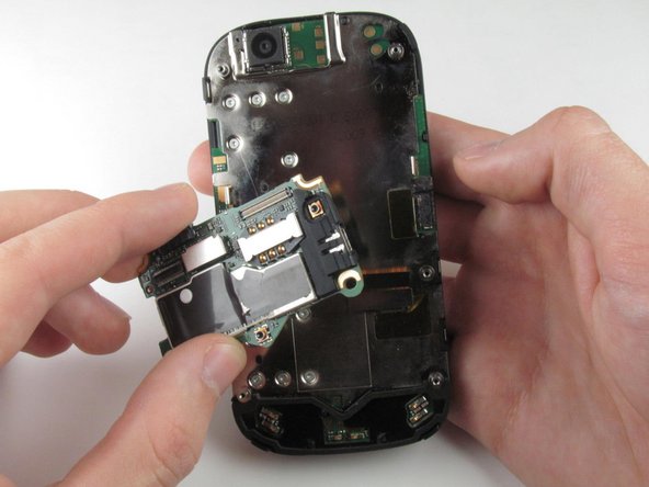
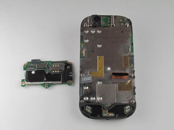
    • Press your thumb against the orange power cable and pull it down slowly to disconnect the power cable from the bottom of the keyboard.

    • The rear casing and the rest of the phone should now be completely separated.

  9. この手順は未翻訳です。 翻訳を手伝う。

    : 手順 9、 2の画像 1 : 手順 9、 2の画像 2
    • Wedge the plastic opening tool underneath the black display connector and pry it off its socket on the motherboard.

  10. この手順は未翻訳です。 翻訳を手伝う。

    : 手順 10、 2の画像 1 : 手順 10、 2の画像 2
    • Pry the orange keyboard connector from its socket on the motherboard using the edge of the plastic opening tool.

  11. この手順は未翻訳です。 翻訳を手伝う。

    : 手順 11、 3の画像 1 : 手順 11、 3の画像 2 : 手順 11、 3の画像 3
    • Carefully grab the sides of the motherboard with your fingers and remove it from the phone.

  12. この手順は未翻訳です。 翻訳を手伝う。

    : 手順 12、 1の画像 1
    • Remove the ten 3.0 mm T4 Torx screws near the black display cable.

  13. この手順は未翻訳です。 翻訳を手伝う。

    : 手順 13、 3の画像 1 : 手順 13、 3の画像 2 : 手順 13、 3の画像 3
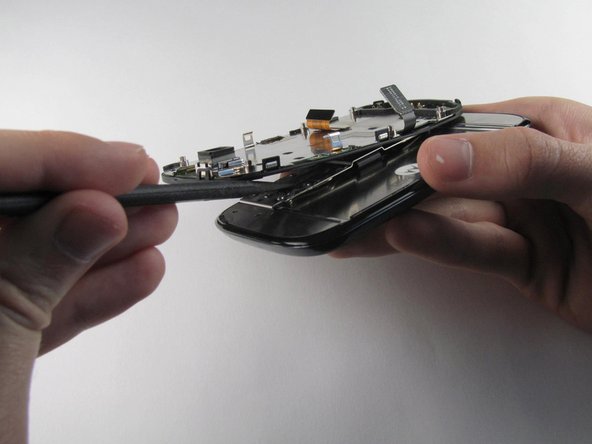
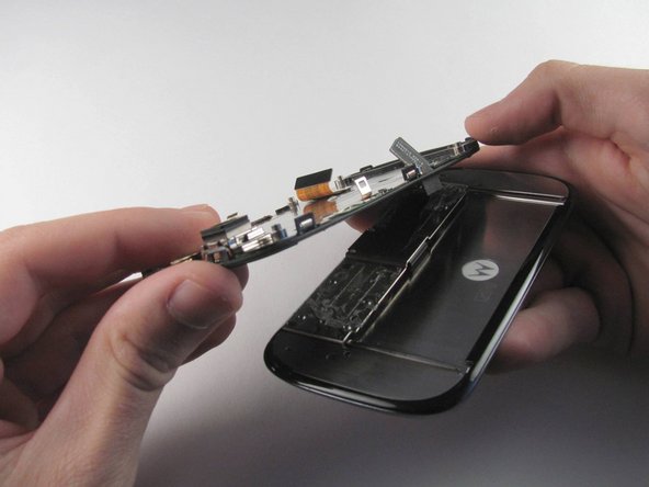
    • Orient the phone so that the edge closest to the camera points towards you and slide out the keyboard.

    • Wedge the tip of a spudger between the keyboard and the display assembly below the camera.

    • With steady pressure, pry the keyboard away from the display assembly.

    • The keyboard and display assembly are glued together, so expect some resistance.

    • Do not completely separate the keyboard and display assembly because the display flex cable still connects them.

  14. この手順は未翻訳です。 翻訳を手伝う。

    : 手順 14、 3の画像 1 : 手順 14、 3の画像 2 : 手順 14、 3の画像 3
    • Grab the display flex cable and gently push it through the notch it is coming out of.

  15. この手順は未翻訳です。 翻訳を手伝う。

    : 手順 15、 3の画像 1 : 手順 15、 3の画像 2 : 手順 15、 3の画像 3
    • Wedge a plastic opening tool underneath one of the metal panels on the underside of the display assembly.

    • Pry upwards and remove the metal panel.

    • Repeat this step for the second metal panel located on the opposite side of the phone.

  16. この手順は未翻訳です。 翻訳を手伝う。

    : 手順 16、 1の画像 1
    • Remove the four 3.0 mm T4 Torx screws at the corners of the phone.

  17. この手順は未翻訳です。 翻訳を手伝う。

    : 手順 17、 3の画像 1 : 手順 17、 3の画像 2 : 手順 17、 3の画像 3
    • Wedge a plastic opening tool between the edge and the black pastic cover on the underside of the display assembly.

    • Run the plastic opening tool along the edges to separate the black plastic cover from the display assembly.

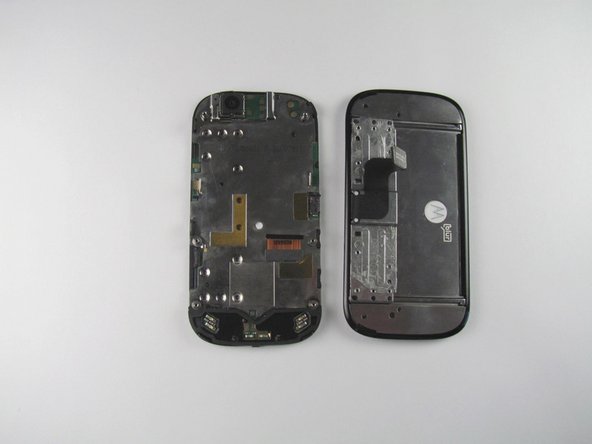
    • Remove the black plastic cover.

  18. この手順は未翻訳です。 翻訳を手伝う。

    : 手順 18、 1の画像 1
    • Remove the six 3.0 mm T4 Torx screws that align on the phone's sides.

  19. この手順は未翻訳です。 翻訳を手伝う。

    : 手順 19、 2の画像 1 : 手順 19、 2の画像 2
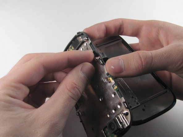
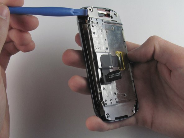
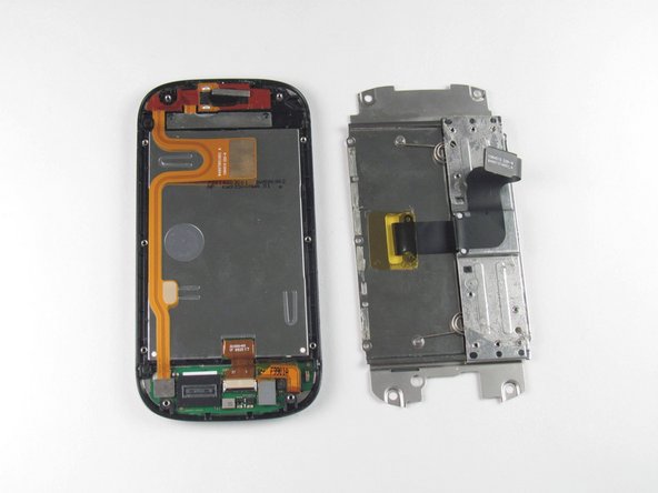
    • Insert a plastic opening tool between the LCD shield plate and a corner of the keyboard slider plate.

    • Pry apart the keyboard slider plate and LCD shield plate.

    • Do not completely separate them: the keyboard slider plate is still connected to the LCD shield plate via the display flex cable.

  20. この手順は未翻訳です。 翻訳を手伝う。

    : 手順 20、 2の画像 1 : 手順 20、 2の画像 2
    • Pry the display flex cable from its connector on the LCD shield plate with a plastic opening tool.

    • Separate the display flex cable from the LCD cover plate.

ゴール

ある他の人がこのガイドを完成しました。

作成者

5人の作成者と共同で作成されました。

Tony Tran

メンバー登録日: 04/14/13

64 ポイント

8のガイドは作成済み

チーム

Cal Poly, Team 10-42, Amido Spring 2013 Cal Poly, Team 10-42, Amido Spring 2013人のメンバー

CPSU-AMIDO-S13S10G42

4 メンバー

16のガイドは作成済み

0 件のコメント

コメントを追加

統計データ:

過去 24時間: 2

過去 7 日: 7

過去 30 日: 8

今までの合計 424