メインコンテンツにスキップ

Dell OptiPlex FX170 Heat Sink Replacement

必要な工具と部品

  1. Dell OptiPlex FX170 Heat Sink Replacement, Case: 手順 1、 1の画像 1
    • With the base stand facing upwards, unscrew the 6mm Phillips #2 screw.

    • Pull the base stand straight up from the device.

  2. Dell OptiPlex FX170 Heat Sink Replacement: 手順 2、 2の画像 1 Dell OptiPlex FX170 Heat Sink Replacement: 手順 2、 2の画像 2
    • Unscrew and remove the eight 4mm Phillips #0 screws (four on top, four on bottom) from the top and bottom of the device.

  3. Dell OptiPlex FX170 Heat Sink Replacement: 手順 3、 3の画像 1 Dell OptiPlex FX170 Heat Sink Replacement: 手順 3、 3の画像 2 Dell OptiPlex FX170 Heat Sink Replacement: 手順 3、 3の画像 3
    • Run the flat side of the spudger along the entire line of the case starting from the back where the power plug and a small screw are located.

    • Use care to not apply excessive force that could damage retaining clips while running the spudger along the case.

  4. Dell OptiPlex FX170 Heat Sink Replacement: 手順 4、 2の画像 1 Dell OptiPlex FX170 Heat Sink Replacement: 手順 4、 2の画像 2
    • Once the clips have been released, gently disengage the cover from the rest of case by pulling in opposite directions.

  5. Dell OptiPlex FX170 Heat Sink Replacement, RAM: 手順 5、 2の画像 1 Dell OptiPlex FX170 Heat Sink Replacement, RAM: 手順 5、 2の画像 2
    • Using fingers, push the clips on either side of the RAM. The RAM will pop up at a 45 degree angle when both clips are disengaged.

  6. Dell OptiPlex FX170 Heat Sink Replacement: 手順 6、 1の画像 1
    • Lift and pull out the RAM.

  7. Dell OptiPlex FX170 Heat Sink Replacement, Memory Board: 手順 7、 1の画像 1
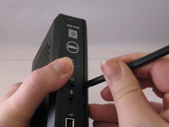
    • Using the spudger, gently push on the underside of the memory board to loosen it. Gently grasp each side and pull up to release the memory board.

  8. Dell OptiPlex FX170 Heat Sink Replacement, CMOS Battery: 手順 8、 1の画像 1
    • To remove the battery, pull up on the connector that is plugged into the motherboard.

  9. Dell OptiPlex FX170 Heat Sink Replacement, Motherboard: 手順 9、 2の画像 1 Dell OptiPlex FX170 Heat Sink Replacement, Motherboard: 手順 9、 2の画像 2
    • Remove the two 4mm Phillips #00 screws that are along the back of the case.

  10. Dell OptiPlex FX170 Heat Sink Replacement: 手順 10、 1の画像 1
    • Remove the two foam bumpers that lie on top of the two front USB ports with fingers. Do not throw them away.

  11. Dell OptiPlex FX170 Heat Sink Replacement: 手順 11、 2の画像 1 Dell OptiPlex FX170 Heat Sink Replacement: 手順 11、 2の画像 2
    • Disconnect the speaker cable from the motherboard by gently pulling it straight up to disengage it from the port.

    • Remove the four 4mm Philips #0 screws that secure the motherboard to the case.

    • The screw in the corner where the RAM is located is covered by a small piece of Mylar tape, peel this tape back to reveal the screw. The tweezers can be helpful for this.

  12. Dell OptiPlex FX170 Heat Sink Replacement: 手順 12、 3の画像 1 Dell OptiPlex FX170 Heat Sink Replacement: 手順 12、 3の画像 2 Dell OptiPlex FX170 Heat Sink Replacement: 手順 12、 3の画像 3
    • Gently grasp the motherboard by the heat sink (the black finned piece). Lift the motherboard at an angle such that the ports along the back side come up first.

    • Continue lifting the motherboard, then slowly tilt the piece off to the right to break the Mylar tape over the front USB ports.

    • Be careful when handling the motherboard to prevent electro-static discharge (ESD) damage. If the motherboard is being removed as part of a prerequisite, place the motherboard into a bag designed to prevent a build up of a static charge (usually referred to as a static bag).

  13. Dell OptiPlex FX170 Heat Sink Replacement, Replacing the Heat Sink: 手順 13、 1の画像 1
    • On the back side of the motherboard, use the tweezers to squeeze the four protruding clips. These should be in the same position as the four black buttons recessed into the heat sink (when viewed from the front).

  14. Dell OptiPlex FX170 Heat Sink Replacement: 手順 14、 1の画像 1
    • Grab the heat sink and motherboard.

    • Gently pull the heat sink away from the board.

    • When replacing the heat sink, be sure to apply a new layer of thermal compound to the CPU to avoid overheat damage.

    • To reattach the heat sink: line the four clips up with the appropriate holes in the motherboard then simply push down on them to push them through to board. There should be a small click when each one is engaged.

終わりに

To reassemble your device, follow these instructions in reverse order.

3 の人々がこのガイドを完成させました。

作成者

3人の作成者と共同で作成されました。

Jess J Cunning

メンバー登録日: 01/13/15

247 ポイント

2のガイドは作成済み

チーム

Eastern Washington University, Team 1-4, Carnegie Winter 2015 Eastern Washington University, Team 1-4, Carnegie Winter 2015人のメンバー

EWU-CARNEGIE-W15S1G4

3 メンバー

13のガイドは作成済み

0 件のコメント

コメントを追加

統計データ:

過去 24時間: 1

過去 7 日: 3

過去 30 日: 3

今までの合計 1,233