メインコンテンツにスキップ

Dell Alienware M17x R4 Memory Modules Replacement

必要な工具と部品

  1. Dell Alienware M17x R4 Memory Modules Replacement, Remove the Screws: 手順 1、 1の画像 1
    • WARNING: Before working inside your computer, read the safety information that shipped with your computer and follow the steps in Before You Begin.

    • Remove the screws that secure the memory-module cover to the palm rest assembly.

  2. Dell Alienware M17x R4 Memory Modules Replacement, Popping Up the Memory Module: 手順 2、 1の画像 1
    • CAUTION: To prevent damage to the memory-module connector, do not use tools to spread the memory module securing clips.

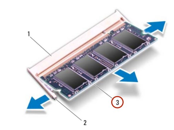
    • Use your fingertips to carefully spread apart the securing clips on each end of the memory-module connector until the memory module pops up.

  3. Dell Alienware M17x R4 Memory Modules Replacement, Removing the Memory Module: 手順 3、 2の画像 1 Dell Alienware M17x R4 Memory Modules Replacement, Removing the Memory Module: 手順 3、 2の画像 2
    • Remove the memory module from the memory-module connector.

  4. Dell Alienware M17x R4 Memory Modules Replacement, Align the Notch: 手順 4、 1の画像 1
    • NOTE: If you need to install memory modules in two connectors, install a memory module in the lower connector before you install a memory module in the upper connector.

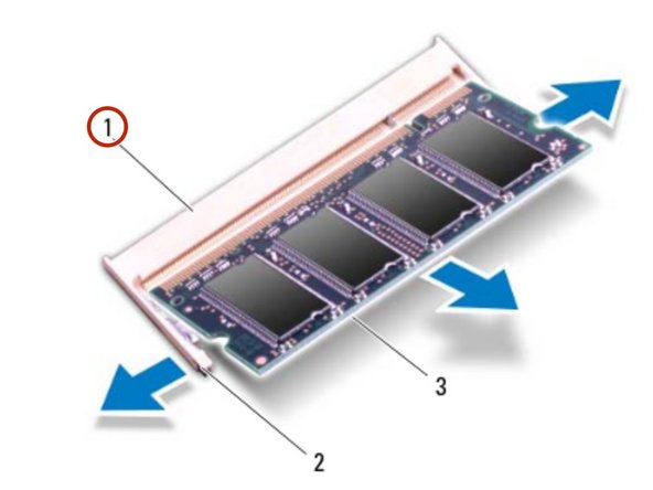
    • Align the notch in the NEW memory module with the tab on the memory-module connector.

  5. Dell Alienware M17x R4 Memory Modules Replacement, Installing the Memory Module: 手順 5、 1の画像 1
    • Slide the memory module firmly into the connector at a 45-degree angle, and press the memory module down until it clicks into place. If you do not hear the click, remove the memory module and reinstall it.

  6. Dell Alienware M17x R4 Memory Modules Replacement, Align the Screw Holes: 手順 6、 1の画像 1
    • NOTE: If the memory module is not installed properly, the computer may not boot.

    • Align the screw holes on the memory-module cover with the screw holes on the palm rest assembly.

  7. Dell Alienware M17x R4 Memory Modules Replacement, Replace the Screws: 手順 7、 1の画像 1
    • Replace the screws that secure the memory-module cover to the palm rest assembly.

終わりに

To reassemble your device, follow these instructions in reverse order.

作成者

1人の作成者と共同作成されました。

Terrence15

メンバー登録日: 12/18/17

79,121 ポイント

441のガイドは作成済み

チーム

RampUP America, Inc. RampUP America, Inc.人のメンバー

Community

42 メンバー

1,985のガイドは作成済み

0 件のコメント

コメントを追加

統計データ:

過去 24時間: 0

過去 7 日: 0

過去 30 日: 3

今までの合計 828