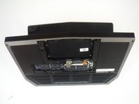
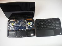
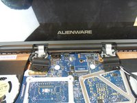
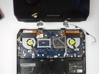
メインコンテンツにスキップ

Dell Alienware 13 Computer Base Replacement

必要な工具と部品

  1. Dell Alienware 13 Computer Base Replacement, Base Panel: 手順 1、 1の画像 1
    • Working on an electrical device while plugged in can cause injury due to electrical shock. Ensure that all external power is disconnected from the device.

    • Close the device and turn the device over.

  2. Dell Alienware 13 Computer Base Replacement: 手順 2、 1の画像 1
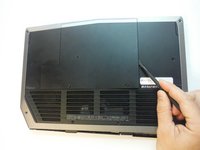
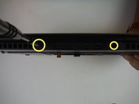
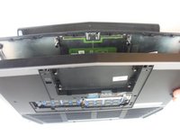
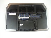
    • Remove (2) 5 mm Phillips head screws attaching the small access panel to the base using a Phillips # 1 screwdriver.

    • The (2) screws are attached to the base panel with retaining clips and won't completely detach from the panel.

  3. Dell Alienware 13 Computer Base Replacement: 手順 3、 3の画像 1 Dell Alienware 13 Computer Base Replacement: 手順 3、 3の画像 2 Dell Alienware 13 Computer Base Replacement: 手順 3、 3の画像 3
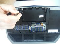
    • Remove the small access panel using a heavy duty spudger.

  4. Dell Alienware 13 Computer Base Replacement, Computer Base: 手順 4、 2の画像 1 Dell Alienware 13 Computer Base Replacement, Computer Base: 手順 4、 2の画像 2
    • Disconnect the battery cable from the battery cable terminal.

  5. Dell Alienware 13 Computer Base Replacement: 手順 5、 1の画像 1
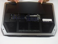
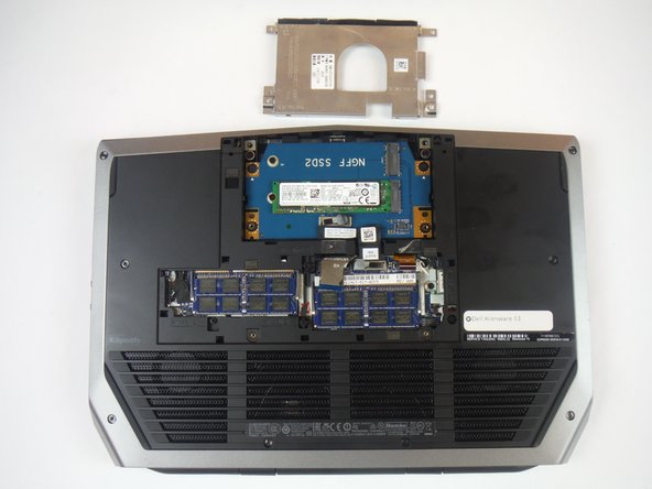
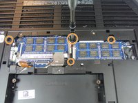
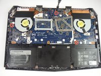
    • Remove (4) 6 mm Phillips head screws from the solid-state metal drive bracket, using a Phillips # 1 screwdriver.

  6. Dell Alienware 13 Computer Base Replacement: 手順 6、 2の画像 1 Dell Alienware 13 Computer Base Replacement: 手順 6、 2の画像 2
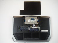
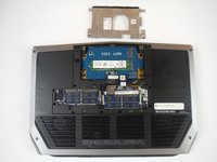
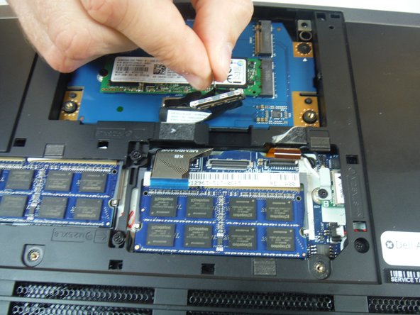
    • Grab the pull tab to pivot the solid-state drive bracket upwards. Remove the bracket from the computer base.

  7. Dell Alienware 13 Computer Base Replacement: 手順 7、 2の画像 1 Dell Alienware 13 Computer Base Replacement: 手順 7、 2の画像 2
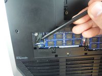
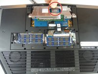
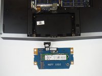
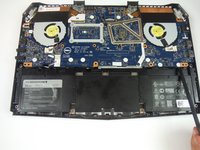
    • Using the pull tab, disconnect the black solid-state drive cable from the system board.

  8. Dell Alienware 13 Computer Base Replacement: 手順 8、 1の画像 1
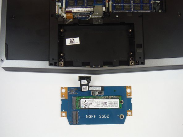
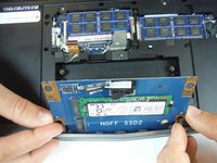
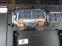
    • Remove (2) 3 mm Phillips head screws, using a Phillips # 0 screwdriver, that connect the solid-state drive assembly to the computer base.

  9. Dell Alienware 13 Computer Base Replacement: 手順 9、 2の画像 1 Dell Alienware 13 Computer Base Replacement: 手順 9、 2の画像 2
    • Lift up on the solid-state drive assembly to remove it from the computer base.

  10. Dell Alienware 13 Computer Base Replacement: 手順 10、 2の画像 1 Dell Alienware 13 Computer Base Replacement: 手順 10、 2の画像 2
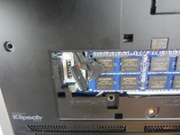
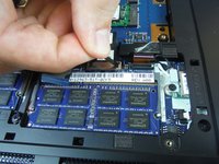
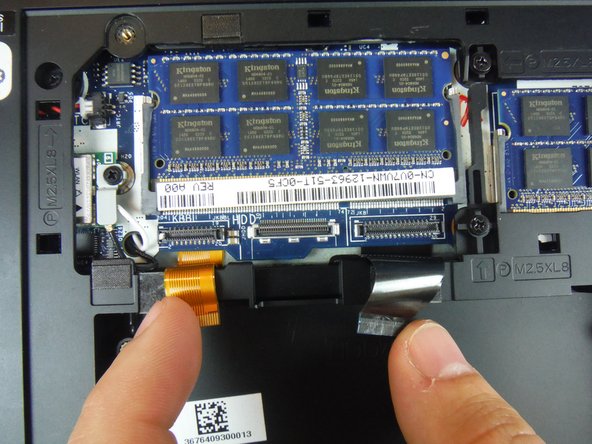
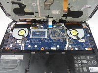
    • Locate two cables labeled, "KB Backlight" (orange) and "KB Membrane" (black). Lift up on the latches to disconnect the cables from the system board.

    • The latches that connect the cables to the system board are very delicate. Handle with care to avoid damaging them.

  11. Dell Alienware 13 Computer Base Replacement: 手順 11、 3の画像 1 Dell Alienware 13 Computer Base Replacement: 手順 11、 3の画像 2 Dell Alienware 13 Computer Base Replacement: 手順 11、 3の画像 3
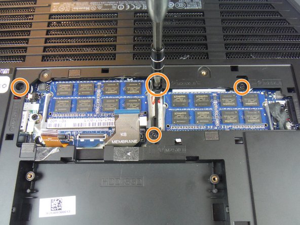
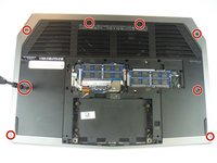
    • Remove (8) 9 mm Phillips head screws using a Phillips # 1 screwdriver, that secures the palm-rest assembly to the computer base.

    • Remove (4) 8 mm Phillips head screws using a Phillips # 1 screwdriver.

    • Remove (2) 7 mm Phillips head screws using a Phillips # 1 screwdriver.

  12. Dell Alienware 13 Computer Base Replacement: 手順 12、 2の画像 1 Dell Alienware 13 Computer Base Replacement: 手順 12、 2の画像 2
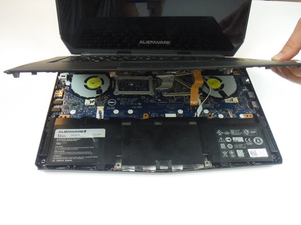
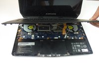
    • Lift the computer base slightly towards you and push the release tabs on the palm-rest assembly until it pops out using a spudger.

  13. Dell Alienware 13 Computer Base Replacement: 手順 13、 3の画像 1 Dell Alienware 13 Computer Base Replacement: 手順 13、 3の画像 2 Dell Alienware 13 Computer Base Replacement: 手順 13、 3の画像 3
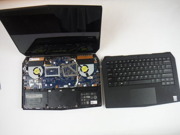
    • Turn the computer over and open the display as far as possible.

    • Using a plastic spudger, pry up along the edges of the palm-rest assembly.

    • Gently lift the palm-rest assembly.

  14. Dell Alienware 13 Computer Base Replacement: 手順 14、 3の画像 1 Dell Alienware 13 Computer Base Replacement: 手順 14、 3の画像 2 Dell Alienware 13 Computer Base Replacement: 手順 14、 3の画像 3
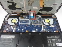
    • Lift the connector latch and disconnect the power-button board cable from the system board. Identified as a cable with a blue tab.

    • Lift the palm-rest assembly off the computer base.

  15. Dell Alienware 13 Computer Base Replacement: 手順 15、 3の画像 1 Dell Alienware 13 Computer Base Replacement: 手順 15、 3の画像 2 Dell Alienware 13 Computer Base Replacement: 手順 15、 3の画像 3
    • Open the display as far as possible.

    • Remove (2) 3 mm Phillips head screws, using a Phillips head #0 screwdriver, that secure the hinge caps to the display hinges.

    • Slide and lift the hinge caps off the display hinges.

  16. Dell Alienware 13 Computer Base Replacement: 手順 16、 2の画像 1 Dell Alienware 13 Computer Base Replacement: 手順 16、 2の画像 2
    • Close the display and turn the computer over.

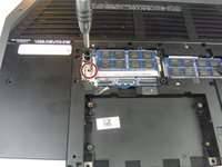
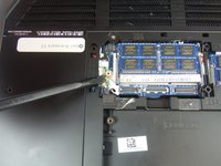
    • Remove (1) 2 mm Phillips head screw, using a Phillips head # 0 screwdriver, that secures the wireless-card bracket to the wireless card.

  17. Dell Alienware 13 Computer Base Replacement: 手順 17、 2の画像 1 Dell Alienware 13 Computer Base Replacement: 手順 17、 2の画像 2
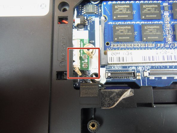
    • Disconnect the antenna cables from the wireless card using a heavy duty spudger. The wires can be removed by applying a force directed upward, away from the device.

  18. Dell Alienware 13 Computer Base Replacement: 手順 18、 3の画像 1 Dell Alienware 13 Computer Base Replacement: 手順 18、 3の画像 2 Dell Alienware 13 Computer Base Replacement: 手順 18、 3の画像 3
    • Turn the computer over and open the display.

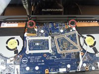
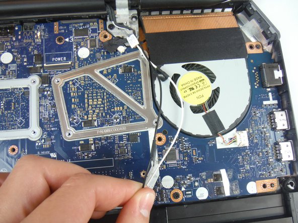
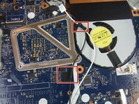
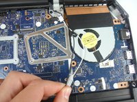
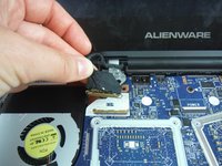
    • Peel off the adhesive tapes that secure the antenna cables to the system board.

    • Make note of how the cables are routed before removing any cables from their routing guide.

  19. Dell Alienware 13 Computer Base Replacement: 手順 19、 3の画像 1 Dell Alienware 13 Computer Base Replacement: 手順 19、 3の画像 2 Dell Alienware 13 Computer Base Replacement: 手順 19、 3の画像 3
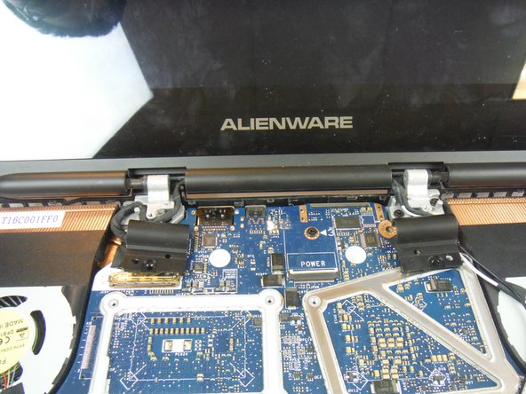
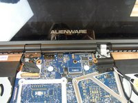
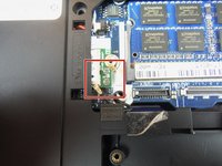
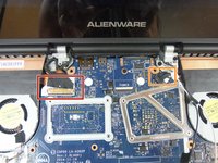
    • Lift the connector latch and disconnect the display cable from the system board.

    • Disconnect the logo-board cable from the system board.

    • Remove the antenna cables, display cable, and logo-board cable from the routing guides on the display hinges.

  20. Dell Alienware 13 Computer Base Replacement: 手順 20、 3の画像 1 Dell Alienware 13 Computer Base Replacement: 手順 20、 3の画像 2 Dell Alienware 13 Computer Base Replacement: 手順 20、 3の画像 3
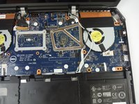
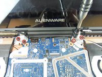
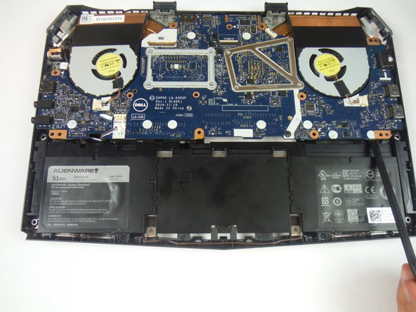
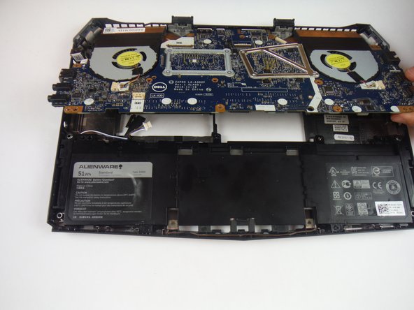
    • Remove (4) 8 mm Phillips head screws, using a Phillips # 1 screwdriver, that secure the display assembly to the computer base.

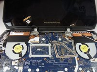
    • Lift the display assembly off the computer base.

  21. Dell Alienware 13 Computer Base Replacement: 手順 21、 2の画像 1 Dell Alienware 13 Computer Base Replacement: 手順 21、 2の画像 2
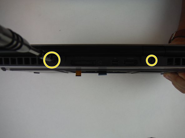
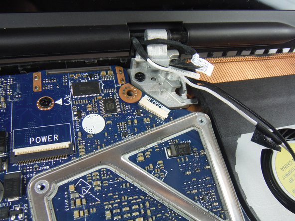
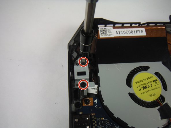
    • Remove the (2) 6 mm Phillips head screws securing the power adapter port bracket with a #1 Phillips screwdriver.

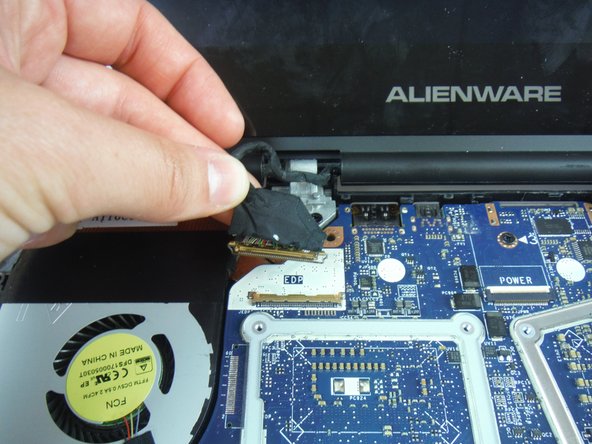
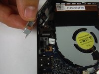
    • Lift and remove the power adapter port bracket.

  22. Dell Alienware 13 Computer Base Replacement: 手順 22、 1の画像 1
    • Lift up and remove the power adapter port from the computer base.

  23. Dell Alienware 13 Computer Base Replacement: 手順 23、 2の画像 1 Dell Alienware 13 Computer Base Replacement: 手順 23、 2の画像 2
    • Disconnect the speaker cable connector from the service board.

  24. Dell Alienware 13 Computer Base Replacement: 手順 24、 3の画像 1 Dell Alienware 13 Computer Base Replacement: 手順 24、 3の画像 2 Dell Alienware 13 Computer Base Replacement: 手順 24、 3の画像 3
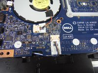
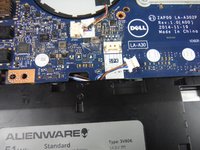
    • Remove (3) 6 mm Phillips head screws securing the service board with a #1 Phillips screwdriver.

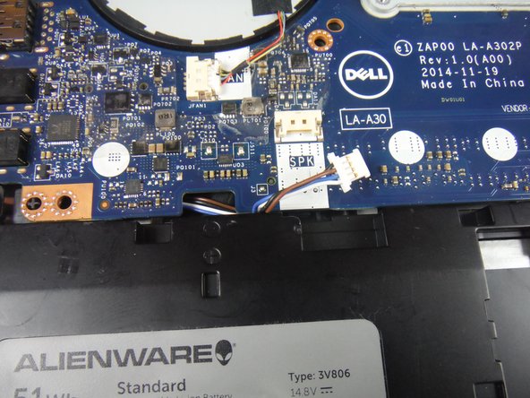
    • Lift up on the service board assembly using a heavy duty spudger and slide the board towards the battery to remove from the base.

終わりに

To reassemble your device, follow these instructions in reverse order.

2 の人々がこのガイドを完成させました。

作成者

2人の作成者と共同で作成されました。

Adam Russell

メンバー登録日: 09/26/16

898 ポイント

6のガイドは作成済み

チーム

USF Tampa, Team 14-2, Eyestone Fall 2016 USF Tampa, Team 14-2, Eyestone Fall 2016人のメンバー

USFT-EYESTONE-F16S14G2

3 メンバー

7のガイドは作成済み

0 件のコメント

コメントを追加

統計データ:

過去 24時間: 0

過去 7 日: 0

過去 30 日: 5

今までの合計 969