メインコンテンツにスキップ

D-Link DCS-5222L Motherboard Replacement

必要な工具と部品

  1. D-Link DCS-5222L Motherboard Replacement, Motherboard: 手順 1、 2の画像 1 D-Link DCS-5222L Motherboard Replacement, Motherboard: 手順 1、 2の画像 2
    • Remove the four rubber feet on the bottom of the camera using your fingers or a pair of tweezers.

  2. D-Link DCS-5222L Motherboard Replacement: 手順 2、 1の画像 1
    • Using a #1 Phillips screwdriver, remove the four 7mm screws that are exposed by the removed feet.

  3. D-Link DCS-5222L Motherboard Replacement: 手順 3、 2の画像 1 D-Link DCS-5222L Motherboard Replacement: 手順 3、 2の画像 2
    • Using your hands, open the camera body by wiggling the bottom free from the upper shell.

    • Open the shell carefully, as the motherboard is attached to the bottom of the body; all of the components in the upper body are accordingly connected to the bottom. Likewise, the WiFi antenna is mounted to the upper shell, but a wire connects it to the motherboard on the bottom of the body.

  4. D-Link DCS-5222L Motherboard Replacement: 手順 4、 3の画像 1 D-Link DCS-5222L Motherboard Replacement: 手順 4、 3の画像 2 D-Link DCS-5222L Motherboard Replacement: 手順 4、 3の画像 3
    • Disconnect the five quick connections attaching the various cables to the motherboard with your fingers or blunt ended tweezers.

  5. D-Link DCS-5222L Motherboard Replacement: 手順 5、 2の画像 1 D-Link DCS-5222L Motherboard Replacement: 手順 5、 2の画像 2
    • Using your soldering iron, heat the antenna contacts on the motherboard until the wire releases.

    • Soldering Irons are hot and can burn you and ignite flammable materials.

  6. D-Link DCS-5222L Motherboard Replacement: 手順 6、 1の画像 1
    • Using a #1 Phillips screwdriver, remove the single 7mm screw holding the motherboard in place.

  7. D-Link DCS-5222L Motherboard Replacement: 手順 7、 3の画像 1 D-Link DCS-5222L Motherboard Replacement: 手順 7、 3の画像 2 D-Link DCS-5222L Motherboard Replacement: 手順 7、 3の画像 3
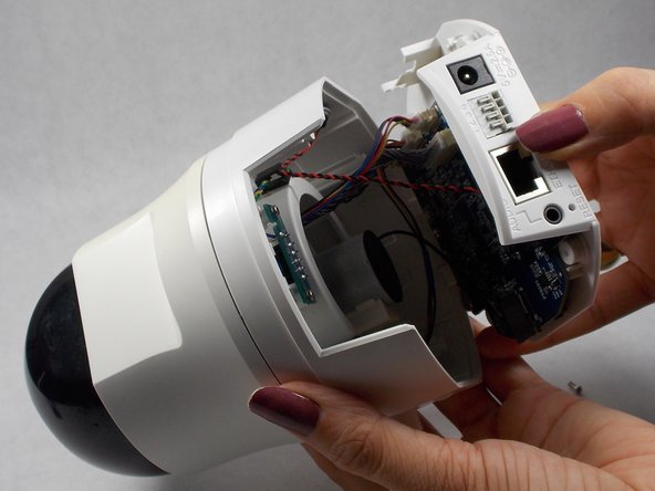
    • Wiggle free the motherboard from the bottom of the body.

    • There are two pegs that limit the motherboard's rotation. Have some patience when wiggling it free.

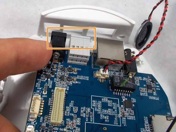
    • The power and ethernet ports have ledges along their top surface. These must be removed from the body at an angle relative to the horizontal.

終わりに

To reassemble your device, follow these instructions in reverse order.

作成者

1人の作成者と共同作成されました。

Ryan Null

メンバー登録日: 10/26/18

377 ポイント

2のガイドは作成済み

チーム

UMass Dartmouth, Team S2-G5, Peak Fall 2018 UMass Dartmouth, Team S2-G5, Peak Fall 2018人のメンバー

UMASSD-PEAK-F18S2G5

3 メンバー

10のガイドは作成済み

0 件のコメント

コメントを追加

統計データ:

過去 24時間: 0

過去 7 日: 2

過去 30 日: 13

今までの合計 1,038