メインコンテンツにスキップ

Crosley CR42 Power Cable Replacement

必要な工具と部品

  1. Crosley CR42 Power Cable Replacement, Power Cable: 手順 1、 2の画像 1 Crosley CR42 Power Cable Replacement, Power Cable: 手順 1、 2の画像 2
    • Turn the device around until you are looking at the line-out port.

    • With a cordless drill or Phillips #0 screwdriver, remove the ten 12-mm screws.

  2. Crosley CR42 Power Cable Replacement: 手順 2、 3の画像 1 Crosley CR42 Power Cable Replacement: 手順 2、 3の画像 2 Crosley CR42 Power Cable Replacement: 手順 2、 3の画像 3
    • Gently remove the back of the device. It should be connected by two wires.

  3. Crosley CR42 Power Cable Replacement: 手順 3、 3の画像 1 Crosley CR42 Power Cable Replacement: 手順 3、 3の画像 2 Crosley CR42 Power Cable Replacement: 手順 3、 3の画像 3
    • Gently remove both wires.

    • After de-threading the antenna wire, remove the back of the device and set it aside.

  4. Crosley CR42 Power Cable Replacement: 手順 4、 3の画像 1 Crosley CR42 Power Cable Replacement: 手順 4、 3の画像 2 Crosley CR42 Power Cable Replacement: 手順 4、 3の画像 3
    • Locate where the power cable connects to the device.

    • Pick up the device and locate the screw holding the small black peg to the device. Unscrew it and set the screw aside.

  5. Crosley CR42 Power Cable Replacement: 手順 5、 3の画像 1 Crosley CR42 Power Cable Replacement: 手順 5、 3の画像 2 Crosley CR42 Power Cable Replacement: 手順 5、 3の画像 3
    • With the pliers, remove the wire connectors. You may need to be forceful

    • It is wise to attach a marking in order to recognize how the wires should be reattached.

  6. Crosley CR42 Power Cable Replacement: 手順 6、 3の画像 1 Crosley CR42 Power Cable Replacement: 手順 6、 3の画像 2 Crosley CR42 Power Cable Replacement: 手順 6、 3の画像 3
    • Pull apart both groups of wires.

    • After getting your replacement power cord, make sure you recognize how the wires should reattach.

  7. Crosley CR42 Power Cable Replacement: 手順 7、 3の画像 1 Crosley CR42 Power Cable Replacement: 手順 7、 3の画像 2 Crosley CR42 Power Cable Replacement: 手順 7、 3の画像 3
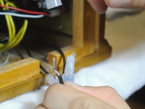
    • Twist the connecting wires together.

    • Attach the twist-on wire connectors to the exposed wires.

終わりに

To reassemble your device, follow these instructions in reverse order.

ある他の人がこのガイドを完成しました。

作成者

7人の作成者と共同で作成されました。

Eric Dybsetter

メンバー登録日: 01/26/14

175 ポイント

1ガイドが承認済み

チーム

Cal Poly, Team 1-38, Maness Winter 2014 Cal Poly, Team 1-38, Maness Winter 2014人のメンバー

CPSU-MANESS-W14S1G38

4 メンバー

5のガイドは作成済み

0 件のコメント

コメントを追加

統計データ:

過去 24時間: 1

過去 7 日: 6

過去 30 日: 16

今までの合計 6,295