メインコンテンツにスキップ

Constructing a Capacitor Discharge Tool

必要な工具と部品

  1. Constructing a Capacitor Discharge Tool, Constructing a Capacitor Discharge Tool: 手順 1、 1の画像 1
    • To construct a capacitor discharge tool, first gather the necessary materials. These include:

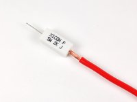
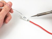
    • Two lengths of wire. Minimum wire requirements is 12AWG, 600 volt rating for large electrolytic capacitors used in power supplies, electric motor start circuits and camera flash circuitry

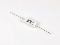
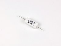
    • A resistor rated to dissipate the amount of thermal energy created when discharging the capacitor. Minimum requirements for resistor is 2k OHM 5w for small capacitors, 20k OHM 5w for large electrolytic capacitors used in power supplies, electric motor start circuits and camera flash circuitry.
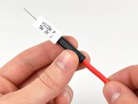
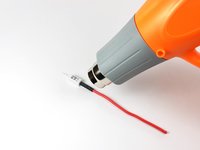
    • Shrink tubing

  2. Constructing a Capacitor Discharge Tool: 手順 2、 2の画像 1 Constructing a Capacitor Discharge Tool: 手順 2、 2の画像 2
    • Begin the process by stripping one side end of each length of wire.

    • To ensure a solid solder joint, strip at least .25" of insulation off the wire.

  3. Constructing a Capacitor Discharge Tool: 手順 3、 2の画像 1 Constructing a Capacitor Discharge Tool: 手順 3、 2の画像 2
    • Next, trim both of the leads leaving the resistor to match the length of insulation stripped off the wires in the previous step.

  4. Constructing a Capacitor Discharge Tool: 手順 4、 3の画像 1 Constructing a Capacitor Discharge Tool: 手順 4、 3の画像 2 Constructing a Capacitor Discharge Tool: 手順 4、 3の画像 3
    • Join the lead leaving the resistor to the stripped end of the wire by twisting the two together.

    • The wire we are using is quite thick, so we inserted the resistor lead down the center of the conductor portion of the wire and twisted the wire against it as tightly as possible.

    • Solder the wire to the resistor.

    • It is essential that enough solder flows through the wire to create a permanent bond between the two pieces.

  5. Constructing a Capacitor Discharge Tool: 手順 5、 2の画像 1 Constructing a Capacitor Discharge Tool: 手順 5、 2の画像 2
    • Slide a section of shrink tubing up the wire, making sure to completely cover up the solder joint and any exposed wire.

    • Use a heat gun or lighter to shrink the tubing over the joint, making sure it is positioned to cover all exposed wire.

  6. Constructing a Capacitor Discharge Tool: 手順 6、 1の画像 1
    • Repeat the above process for the other side of the resistor.

    • To complete the discharge tool, strip the ends of the wires.

    • To discharge from small points, it may be helpful to cut the exposed ends of wire into a point shape and solder them to maintain the shape. Alternatively, the probes commonly used on multimeters can be soldered to the wires to create a more precise discharge tool.

    • For large electrolytic capacitors used in power supplies, electric motor start circuits, and camera flash units, you may want to solder one end to a large alligator clip and the other to a well insulated screwdriver.

ゴール

134 の人々がこのガイドを完成させました。

作成者

9人の作成者と共同で作成されました。

Andrew Bookholt

585,500 ポイント

619のガイドは作成済み

11 件のコメント

This article is by far the best I've read. I have made these in the past and had to get past the amount of words used to describe what needed to be done with what. This article is straight to the point and the tips ( using alligator clip ) are excellent.

Paul Kriner - 返信

I get the basics and can build something more to fit my needs, with what you have instructed

puckhead22 - 返信

hi

i have one query, if it is possible to discharge the capacitor in 12V 1 A power supply..? if i cut of the power, the power supply discharge the power around 6 sec but i need to discharge it with in 1 sec ..? this is possible or Not...?

prakashkumar - 返信

Thank you! I have been looking for a good diy discharge probe....I also used overlapping large size heat shrink to strengthen the joint at the ceramic resistor to prevent failure at a bad time.

doorabull2 - 返信

コメントを追加

統計データ:

過去 24時間: 42

過去 7 日: 377

過去 30 日: 1,675

今までの合計 209,052